37
L510023-07
Velvet Drive and Hurth 8 Degree Down Angle
Transmissions
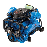
5. Lift the engine into the boat and position it on
the engine bed so that the transmission and
propeller shaft couplings are visibly aligned (no
gap can be seen between the coupling faces
when butted together). Adjust the engine bed
height, if necessary, to obtain proper alignment.
DO NOT use mount adjustments to adjust
engine position at this time.
Figure 33 Coupling Flange Alignment
Velvet Drive and Hurth V-Drive Transmissions
5. Lift the engine into the boat and position it
on the engine bed so that the propeller shaft
protrudes thru the transmission output fl ange
coupling. Install the propeller shaft coupling and
then position the engine so that the couplings are
visibly aligned (no gap can be seen between the
coupling faces when butted together). Adjust the
engine bed height, if necessary, to obtain proper
alignment. DO NOT use mount adjustments to
adjust engine position at this time.
All Transmissions
IMPORTANT: The engine bed must position the
engine so that a minimum of 1/4 in. (6 mm) up-and-
down adjustment still exists on all four (4) mounts
after performing fi nal adjustment. This is necessary
to allow for realigning the engine in the future.
6. Check all four (4) mounts to ensure that they are
still positioned properly, then fasten the mounts
to the engine bed with 1/2 in. (1.27 cm) diameter
lag bolts (of suffi cient length). Tighten the lag
bolts securely.
7. Disconnect the overhead hoist and remove the
sling.
FINAL ENGINE ALIGNMENT
IMPORTANT: Engine alignment MUST BE
RECHECKED with the boat in the water, fuel tanks
fi lled, and with normal load onboard.
You MUST allow 24 hours from the time the boat is
launched until the fi nal engine alignment is checked.
This allows the boat hull to settle into the position
that the engines will run in.
Engine must be aligned so that the transmission and
propeller shaft coupling center lines are aligned and
coupling faces are parallel within 0.003 in. (0.07 mm).
This applies to installations with solid couplings, as
well as fl exible couplings.
1. Check the mating faces on the transmission and
propeller shaft couplings to make sure they are
clean and fl at.
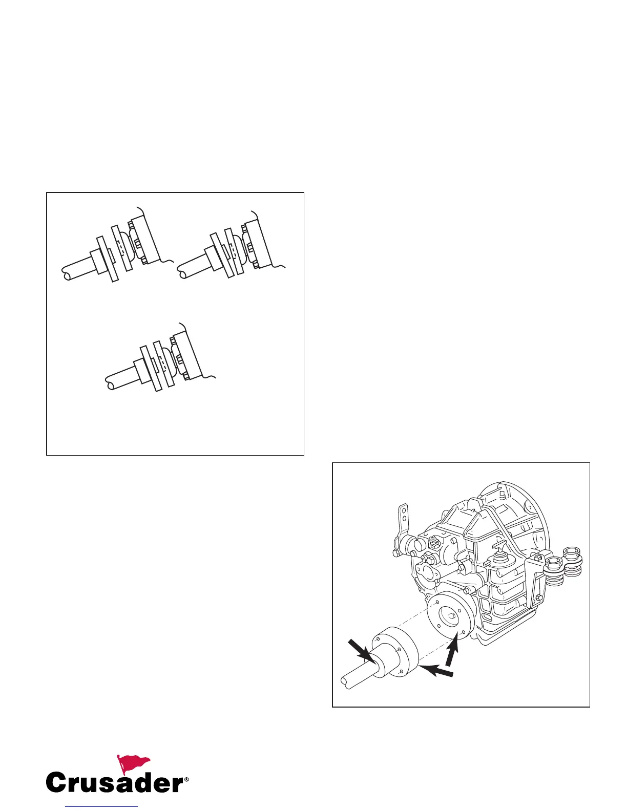
Figure 34 Shaft Mating Surface Check - 8 Degree Down
Angle
OFFSET
MISALIGNMENT
ANGULAR
MISALIGNMENT
PERFECT ALIGNMENT
COUPLING FACES ARE PARALLEL
WITH DISTANCE BETWEEN FACES
EXACTLY THE SAME AT ALL POINTS