36
L510023-07
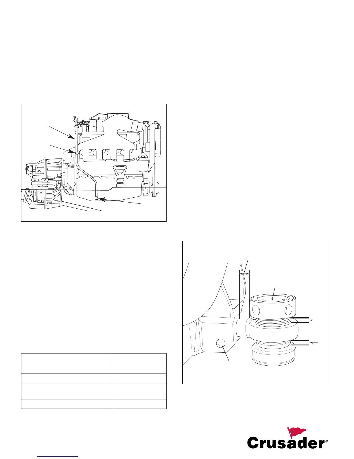
2. Remove the bolt retaining the dipstick mounting
clamp. Then, remove the dipstick fi tting at the
oil pan. Loosen the center bolt and rotate the oil
pan fi tting.
3. Put sealer on the dipstick fi tting threads and
reinstall into the oil pan fi tting. Mount and attach
the dipstick in the same manner as it was
removed from the other side.
4. Fill the engine with oil.
Figure 31 Oil Pan and Dipstick Fittings
Engines Equipped with Hurth and Velvet Drive
5000 Series Transmissions
Engine crankcase oil dipstick can be located either port
or starboard side of the engine, depending on installation
requirements. To move the dipstick, reverse the dipstick
and rubber caps on the dipstick tubes.
ENGINE INSTALLATION
NOTICE TO INSTALLER BEFORE STARTING
INSTALLATION: Read “General Information” and
“Installation Requirements” completely.
TORQUE SPECIFICATIONS
NOTICE: Tighten ALL fasteners (not listed) securely.
Engine Mount Attaching Bolts 45 lb-ft (61 N
.
m)
Fuel Line Inlet Fitting Securely
Trunnion Clamping Bolt and Nut 45 lb-ft (61 N
.
m)
Propeller Shaft Coupling Bolt and
Nut 50 lb-ft (68 N
.
m)
Exhaust Manifold Bolt 20 lb-ft (27 N
.
m)
PRELIMINARY ENGINE ALIGNMENT
(Mount Adjustment Tool - P/N 22165)
1. Remove the lag screws holding the engine to
the shipping pallet. Attach a suitable sling to the
lifting eyes on the engine. Lift the engine from
the pallet with an overhead hoist.
2. Check the tightness of the engine mounts and
re-torque the mount attaching bolts to 45-50 lb-ft
(61-68 N
.
m), if necessary.
IMPORTANT: Engine mounts must be adjusted
as explained in Steps 3 and 4 to center mount
adjustment and establish a uniform height on all
mounts.
3. Check all four (4) engine mounts to ensure that
the distance from the bottom of the mount to
the bottom of the trunnion is as shown. If not,
turn the nylon adjusting sleeve in the direction
required to obtain the proper dimension.
4. Loosen the trunnion clamping bolt and nut on
all four (4) engine mount brackets to ensure the
following:
a. Large diameter of the mount trunnion is
extended as shown.
b. Each mount base is downward. Tighten the
trunnion clamping bolts and nuts slightly to
prevent moving in or out. Mounts must be
free to pivot when installing the engine.
Figure 32 Preliminary Engine Mount Extension
DIPSTICK
TUBE
CLAMP
OIL PAN
FITTING
TRUNNION
BOLT
0.5 in.
(12.5 mm)
3/8 in.
(9.5 mm)
LAG
BOLT