SG250 Owner’s and Service Manual
www.CSCMotorcycles.com
98
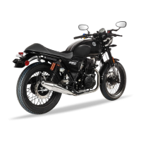
Shut the engine off, disconnect the harness connector shown
above, and measure the resistance between all three leads
(it should be approximately 0.5 ohms; anything between 0.3
ohms and 0.6 ohms is acceptable). If the resistance is
outside the range mentioned above the stator should be
replaced.
If the charging system from the engine crankshaft (i.e., at the yellow leads discussed above) has
appropriate output and resistance, we should next check the output from the rectifier. Find the
connector plug between the rectifier and the battery and check voltage output when the engine is
running. If it is below 13.8 VDC or above 14.5 VDC when you blip the throttle, the rectifier is defective
and it must be replaced.
If the voltage is within the acceptable range (i.e., between 13.8 and 14.5 VDC) but the output at the
battery terminals (with the engine running) is outside this range, the problem lies in the circuit
between the connector plug and the battery. In this situation, you should check for open circuits,
improper connections, or shorts to ground and correct the anomalous condition.
If the engine is not providing the appropriate output AC
voltage or the resistance between the stator leads is too high
(as measured at the connector shown earlier), there is a
problem with the stator, the engine’s internal wiring from
the stator, or the rotor. It will be necessary to remove the
left engine crankcase cover to inspect and correct the
anomalous condition. The photos shown here are from the
TT250 motorcycle; the SG250 is similar.
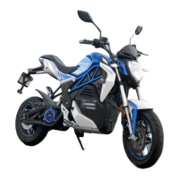
Place a drip pan beneath the engine, as oil will escape from
the engine during this operation, and remove the gear shift
lever with a 10mm wrench.
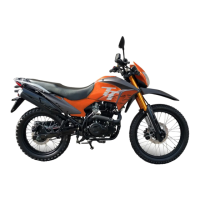
There are several 8mm bolts securing the left engine cover
and the countershaft sprocket cover. Remove all of
them. Note that the bolts are of different lengths. Take care
to note where each bolt is used.