Steering
39
Introduction
The steering on the RZT-S Zero mower is similar to that of other mowers with Cub Cadet’s Syncro Steer Tech-
nology. The Syncro Steer Technology steers by:
1. It steers like any other riding mower by turning the front wheels.
2. It controls the speed and direction of rotation of the rear wheels. On the RZT-S Zero this is accomplished by:
• A hall effect sensor on the left front wheel yoke sends a signal to the Vehicle Control Module (VCM).
• The VCM uses the input signal to determine the steering angle of the front wheels.
• The VCM uses the signal from a Throttle Position Sensor (TPS) to determine how fast the operator wishes
the mower to move and in which direction (forward or reverse).
• The VCM computes the wheel speed and direction need for each rear wheel based on the steering angle
and the TPS.
• The VCM sends a signal to each rear wheel controller, telling it what speed and direction of rotation is
needed at that wheel.
• The controllers then sends a signal to the wheel motors, spinning them at the proper speed.
Wheel alignment
IMPORTANT: Check the tire air pressure and wear before attempting to diagnose any problems with the
steering or tracking of a RZT-S Zero riding mower. If the tire circumferences are not equal
across the same axles, it will greatly affect the performance of the riding mower.
IMPORTANT: All zero turn mowers must have matching tires across the same axle (both front wheels and
both back wheels).
NOTE: The alignment tool kit 759-05013 is required to perform the wheel alignment.
1 Remove the floor pan, following the procedures
described in Chapter 2: Body.
2. Position the steering wheel on the steering shaft.
3. Turn the steering wheel to center the segment
gears.
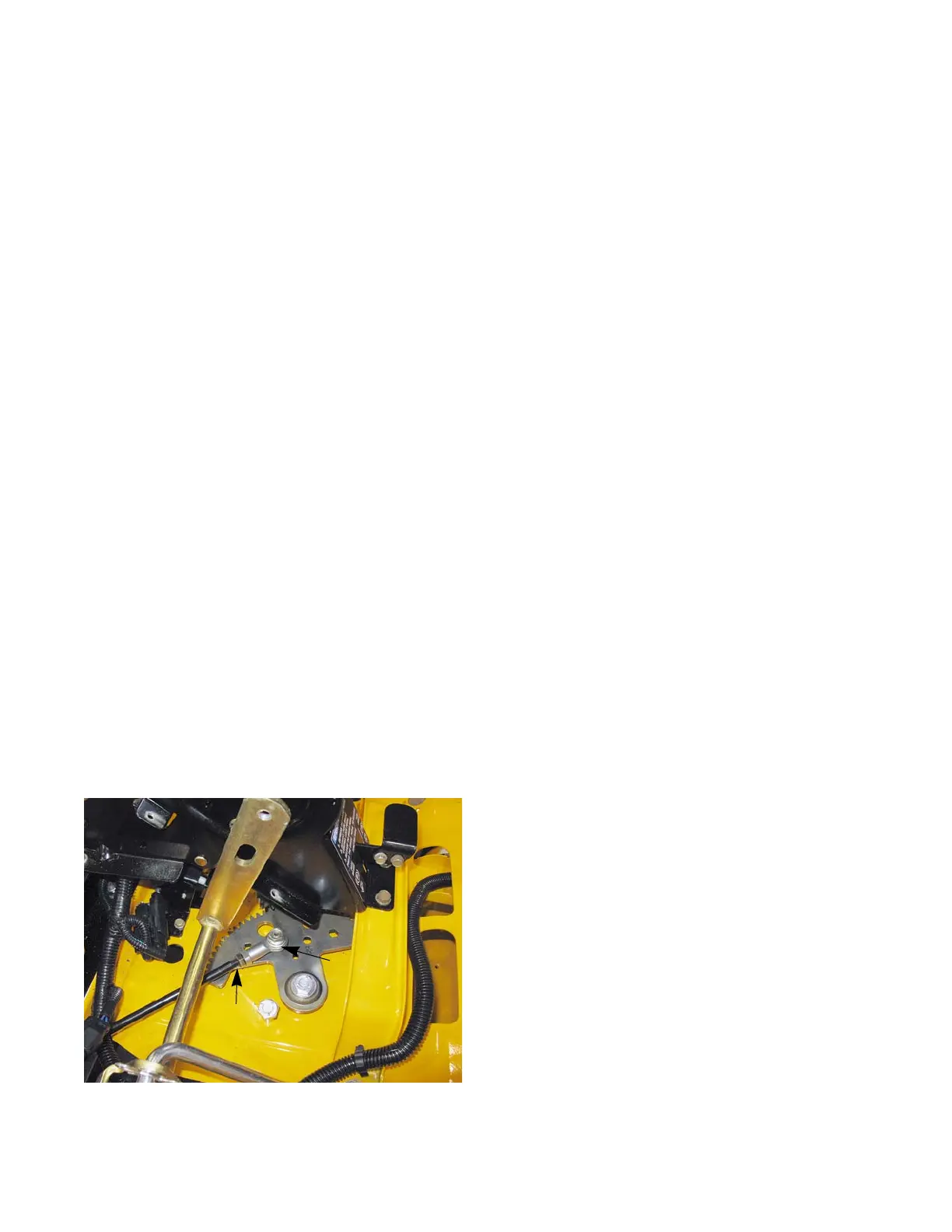
4. Loosen the drag link ball joint jam nuts using a 9/16”
wrench.
5. Disconnect the drag links from the segment gears
using a pair of 9/16” wrenches.
See Figure 4.1.
NOTE: There is a hole in the frame for wrench access the
head of the bolt that holds the ball joint to the seg
-
ment gear.
Figure 4.1
Jam nut
Ball joint
CHAPTER 4: STEERING
 Loading...