Electrical System
71
4. Discharge the pre-charge capacitors.
NOTE: Do not use a high impedance test light for this pro-
cedure. There is a very high likelihood that the
capacitor’s charge will damage it.
4a. Remove the controller cover.
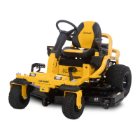
4b. Attach an incandescent test light to the negative
(black) wire attached to the controller.
4c. Touch the probe of the test light to the positive
(red) wire connection on the controller.
NOTE: The test light will light up very brightly, then quickly
dim out. Hold the test light probe in place until the
light goes out.
5. Remove the five wires from the controller.
6. Label each wire with its location.
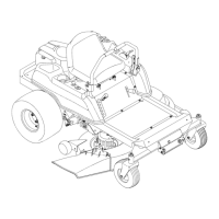
7. Remove the four screws, Figure 5.29, that hold the
controller in place using a #2 Phillips screwdriver.
8. Install the controller by following the previous steps in
reverse order.
9. Tighten the screws that connect the five wires to the
controller to a torque of 21 in lbs (2 Nm).
NOTE: The screws that attach the five wires to the control-
ler thread into a block soldered to the circuit board.
Over torquing these screws will destroy the con
-
troller.
 Loading...