Curtis 1243GEN2 Manual
4
INSTALLATION AND WIRING
MOUNTING THE CONTROLLER
The controller can be oriented in any position, but the location should be
carefully chosen to keep the controller as clean and dry as possible. If a
clean, dry mounting location cannot be found, a cover must be used to
shield the controller from water and contaminants. When selecting the
mounting position, be sure to also take into consideration (1) that access is
needed at the front of the controller to plug the programmer into its connector,
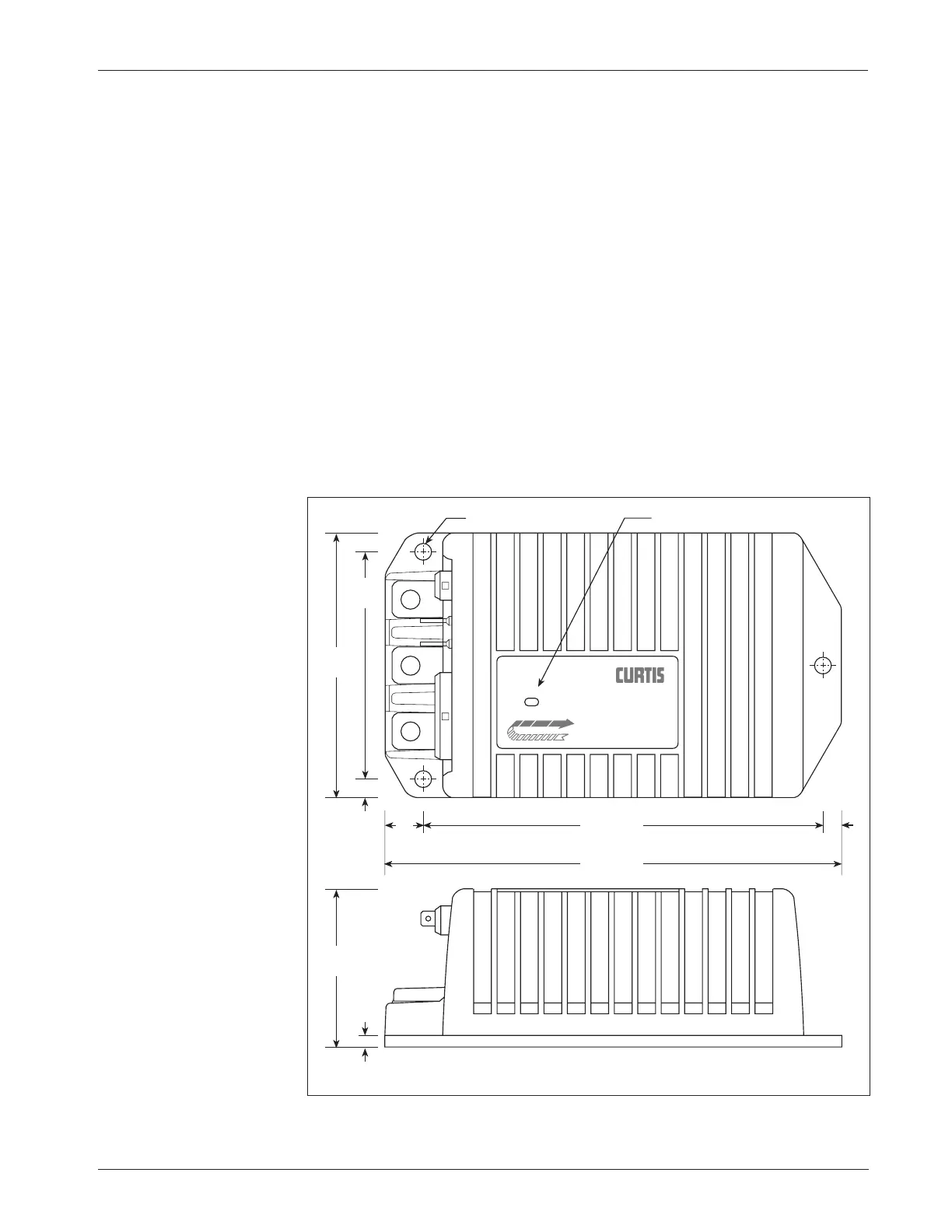
and (2) that the built-in Status LED is visible only through the view port in the
label on top of the controller.
The outline and mounting hole dimensions for the 1243GEN2 controller
are shown in Figure 2. To ensure full rated power, the controller should be
fastened to a clean, flat metal surface with three 6 mm (1/4") diameter screws,
using the holes provided.
2
2 — INSTALLATION & WIRING:
Controller
Fig. 2 Mounting
dimensions, Curtis
1243
GEN2 controller.
Dimensions in millimeters (and inches)
C
L
S
EP
E
X
198 (7.78)
6.4 (0.25) dia., 3 plcs
68
(2.68)
114
(4.50)
173 (6.81)
17
(0.66)
7.9
(0.31)
99
(3.88)
4.8
(0.19)
7.9
(0.31)
STAT U S
Status LED
TRACTION CONTROLLER
TM