Curtis 1243GEN2 Manual
15
2 — INSTALLATION & WIRING:
Spyglass Display
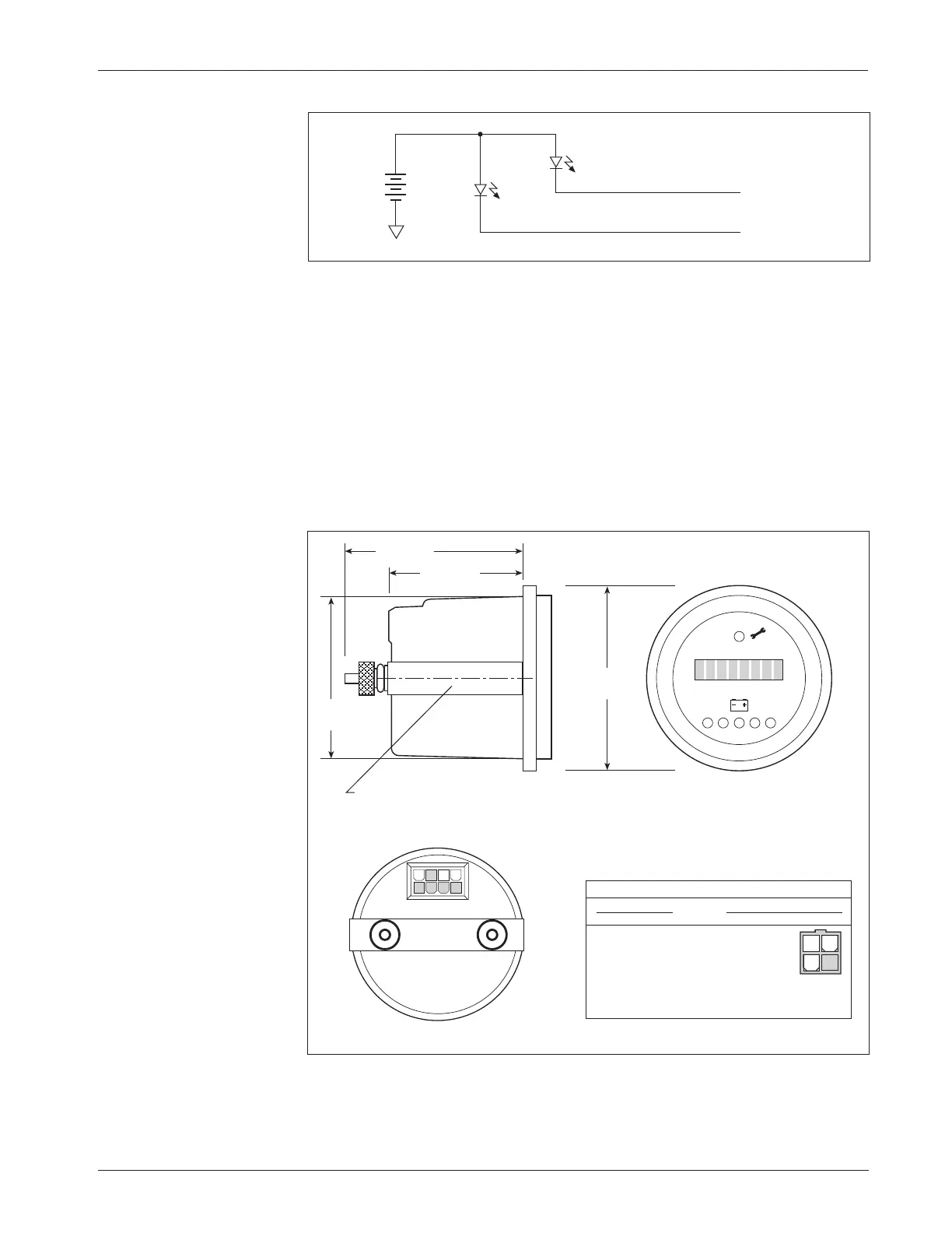
Fig. 11 Wiring for fault
outputs, when used to drive
LEDs. Alternatively, Pin 2
can be used for a pump
meter input, and Pin 3 can
be used to interface an
external enable circuit.
B-
+
-
Fault 1 output (Pin 2)
Fault 2 output (Pin 3)
WIRING: Spyglass Display
The Curtis 840 Spyglass features an 8-character LCD display that sequences
between hourmeter, BDI %, and fault messages. Depending on the model,
either three or six indicator LEDs are also located on the face of the gauge. See
Section 7 (Diagnostics and Troubleshooting) for more information on the
Spyglass displays.
The mating 8-pin connector is Molex 39-01-2085, with 39-00-0039
(18–24 AWG) pins.
Fig. 12 Wiring guide and
mounting dimensions for
Curtis Spyglass (6-LED
model shown; dimensions
and wiring are identical for
the 3-LED model).
SPYGLASS 1243·GEN·2 CONTROLLER
PIN # FUNCTION PIN #
1–4 N.C. –
5 +12V, +15V 4
6 receive data 3
7 N.C. –
8 ground (B+) 2
58
(2.25)
44 (1.75)
8
58 (2.25)
52
(2.0)
“U” clamp for
up to 6 (0.25)
panel thickness
5
4 1
WIRING GUIDE
34
12
0 1
Dimensions in millimeters (and inches)