Curtis 1243GEN2 Manual
11
2 — INSTALLATION & WIRING:
Throttle
0–5V, Current Source, 3-Wire Potentiometer,
and Electronic Throttles (“Type 2”)
With these throttles (“Type 2” in the programming menu) the controller looks
for a voltage signal at the wiper input (Pin 6). Zero speed will correspond to 0 V
and full speed to 5 V (measurements made relative to B-). A voltage source,
current source, 3-wire potentiometer, or electronic throttle can be used with this
throttle type. The wiring for each is slightly different and each has varying levels
of throttle fault detection associated with it.
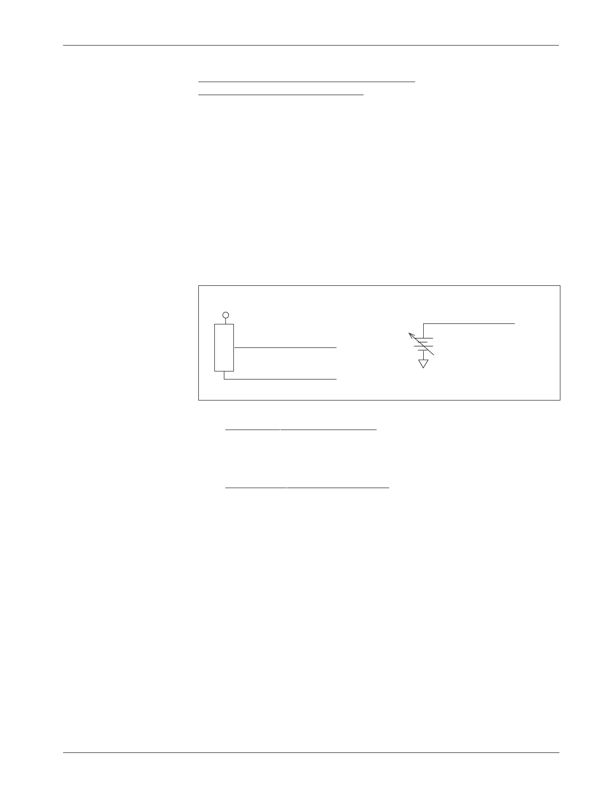
0–5V Throttle
Two ways of wiring the 0–5V throttle are shown in Figure 6. The active range
for this throttle is from 0.2 V (at 0% Throttle Deadband) to 5.0 V (at 100%
Throttle Max), measured relative to B-.
Fig. 6 Wiring for
0–5V throttles (“Type 2”).
Sensor-referenced 0–5V throttles must provide a Pot Low current greater
than 0.65 mA to prevent shutdown due to pot faults. It is recommended that
the maximum Pot Low current be limited to 55 mA to prevent damage to the
Pot Low circuitry.
Ground-referenced 0–5V throttles require setting the Pot Low Fault
parameter (see Section 3, page 38) to Off; otherwise the controller will register
a throttle fault and will shut down. For ground-referenced 0–5V throttles, the
controller will detect open breaks in the wiper input but cannot provide full
throttle fault protection. Also, the controller recognizes the voltage between the
wiper input and B- as the applied throttle voltage and not the voltage from the
voltage source relative to the Pot Low input.
For either throttle input, if the 0–5V throttle input (Pin 6) exceeds 5.5 V
relative to B-, the controller will register a fault and shut down.
+
-
B-
+
SENSOR GROUND
SENSOR OUTPUT (0–5V)
S E N S O R
Pot Low input (Pin 7)
0–5V input (Pin 6)
0–5V input (Pin 6)
Pot Low Fault setting = OFF
☞
Sensor-referenced 0–5V source Ground-referenced 0–5V source