Curtis 1243GEN2 Manual
36
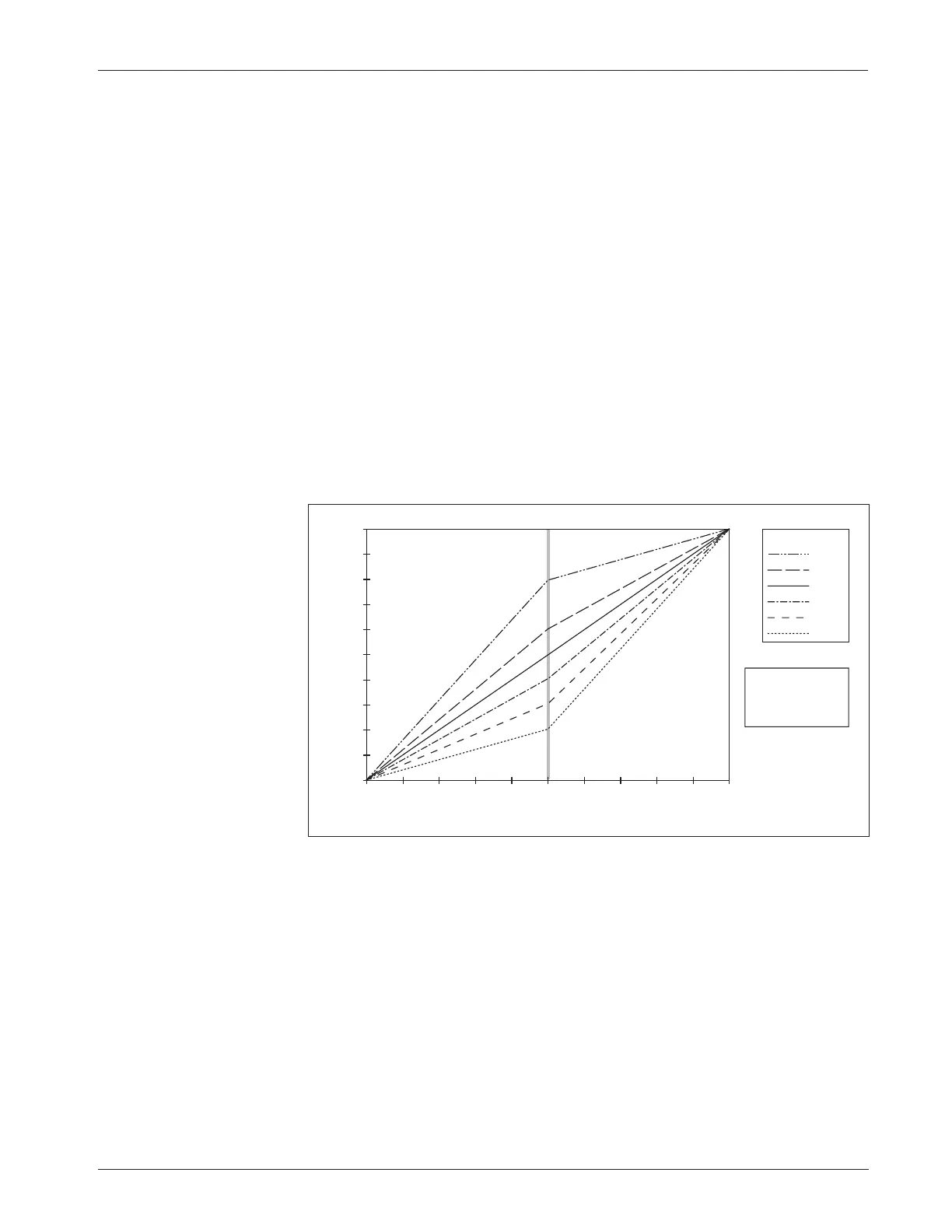
Fig. 17 Throttle maps for
controller with maximum
speed set at 100% and
creep speed set at 0.
THROTTLE INPUT (percent of active range)
CONTROLLER OUTPUT (percent PWM)
80%
60%
50%
40%
30%
20%
THROTTLE MAP
100
90
80
70
60
50
40
30
20
10
0
100908070605040302010 0
SPEED PARAMETERS
0% Creep Speed
100% Max Speed
3 — PROGRAMMABLE PARAMETERS:
Throttle Parameters
THROTTLE MAP
The throttle map parameter modifies the vehicle’s response to the throttle
input. The throttle map parameter’s default setting of 50% provides a linear
output response to throttle position. Values below 50% reduce the controller
output at low throttle, providing enhanced slow speed maneuverability. Values
above 50% give the vehicle a faster, more responsive feel at low throttle.
The throttle map setting can be programmed between 20% and 80%.
The setting refers to the PWM output at half throttle, as a percentage of the
throttle’s full active range. The throttle’s active range is the voltage or resistance
between the 0% modulation point (the throttle deadband threshold) and the
100% modulation point (the throttle max threshold).
With creep speed set at 0 and maximum speed set 100%, a 50% throttle
map setting will give 50% output at half throttle. A throttle map setting of 80%
will give 80% output at half throttle. Six throttle map profiles (20, 30, 40, 50,
60, and 80%) are shown in Figure 17; in all these examples the creep speed is
set at 0 and the maximum speed at 100%.
Changing either of the speed parameters changes the characteristics of the
controller output relative to the throttle input and hence the throttle response.
Controller output is always a percentage of the range defined by the speed
parameters (the range between the creep speed and maximum speed settings).
This means that controller output will begin to increase above the set creep
speed as soon as the throttle exceeds the neutral deadband threshold. Controller
output will continue to increase as the throttle input increases and will reach
maximum output when the throttle input reaches the throttle max threshold.
The maximum controller output at this point is defined by the value of the
maximum speed parameter.