Curtis 1243GEN2 Manual
7
2 — INSTALLATION & WIRING:
Controller
for the M8 bolts. The maximum bolt insertion depth below the surface of the
bus bar is 1.3 cm (1/2"). Bolt shafts exceeding this length may damage the controller.
The torque applied to the bolts should not exceed 16.3 N·m (12 ft-lbs).
Two 1/4" quick connect terminals (S1 and S2) are provided for the
connections to the motor field winding.
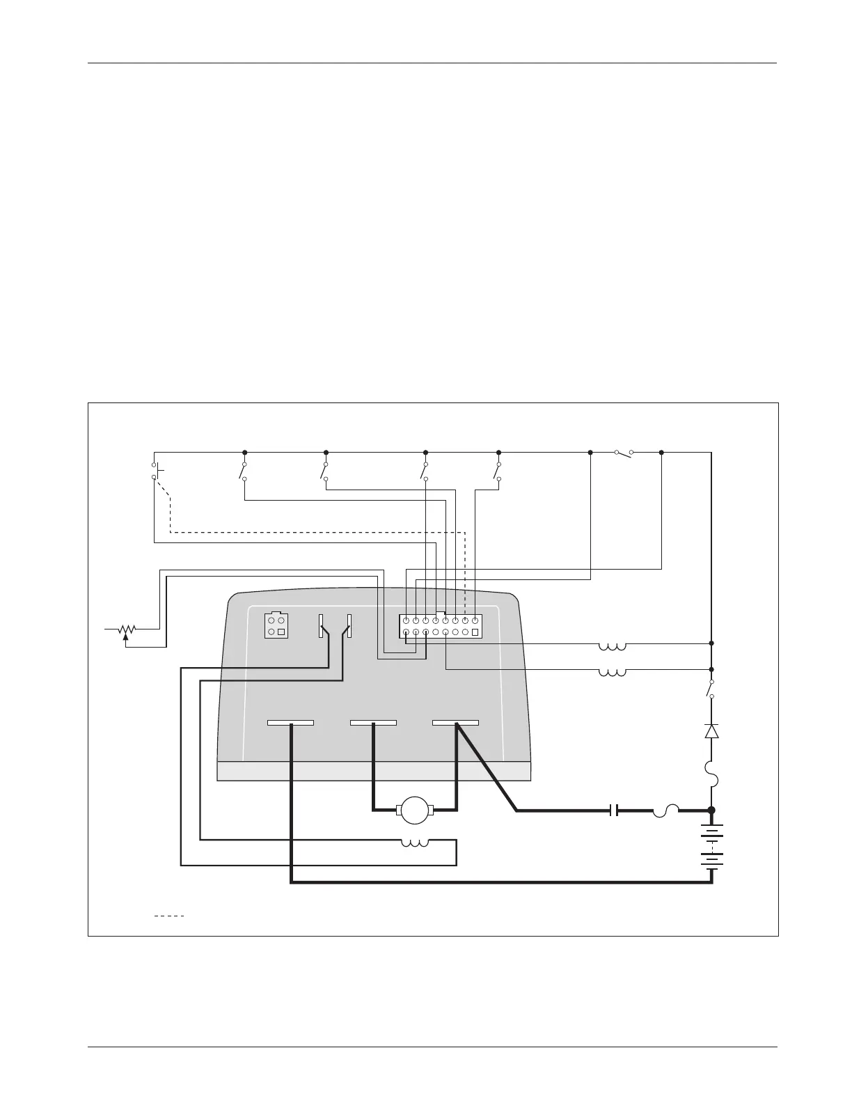
WIRING: Standard Configuration
Figure 3 shows the typical wiring configuration for most applications. For
walkie applications the interlock switch is typically activated by the tiller, and
an emergency reverse switch on the tiller handle provides the emergency reverse
signal.
For rider applications the interlock switch is typically a seat switch or a
foot switch, and there is no emergency reverse.
Fig. 3 Standard wiring configuration, Curtis 1243GEN2 controller.
S1 S2
B- M- B+
INTERLOCK
5 k
Ω
POT
THROTTLE
(TYPICAL)
EMERGENCY
REVERSE
emergency reverse wiring check (optional)
FORWARD
MAIN
CONTACTOR
COIL
POLARITY
PROTECTION
DIODE
REVERSE
MODE
SELECT
1
MODE
SELECT
2
ELECTRO-
MAGNETIC
BRAKE
KEY
SWITCH
POWER
FUSE
A
MAIN
CONTACTOR
B+
B-
A2 A1
S2 S1
CONTROL
FUSE
1
9
8
16