Curtis 1243GEN2 Manual
6
CONNECTIONS
Low Current Connections
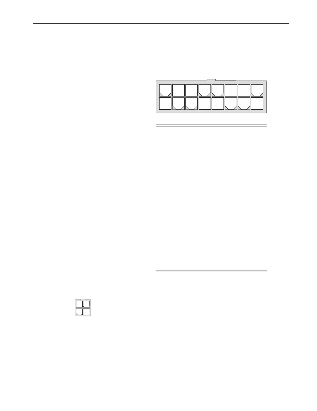
A 16-pin Molex low current connector in the controller provides the low current
logic control connections:
2 — INSTALLATION & WIRING:
Controller
The mating connector is a 16-pin Molex Mini-Fit Jr. connector p/n 39-01-2165
using type 5556 terminals.
A 4-pin low power connector is provided for the handheld programmer. A
complete 1311 programmer kit, including the appropriate connecting cable,
can be ordered from Curtis.
The 4-pin connector can also be used for the Spyglass display. The display
is unplugged when the programmer is used.
High Current Connections
Three tin-plated solid copper bus bars are provided for high current connections
to the battery (B+ and B-) and the motor armature (M-). Cables are fastened to
the bus bars by M8 bolts. The 1243GEN2 case provides the capture nuts required
Pin 1 load sensor input [optional]
Pin 2 Fault 1 output / pump input
Pin 3 Fault 2 output
Pin 4 main contactor driver output
Pin 5 throttle: 3-wire pot high
Pin 6 throttle: 0–5V; pot wiper
Pin 7 throttle: pot low
Pin 8 auxiliary driver output (typically
used for an electromagnetic brake)
Pin 9 Mode Select 2 input
Pin 10 emerg. reverse check output [optional]
Pin 11 reverse input
Pin 12 forward input
Pin 13 emergency reverse input
Pin 14 Mode Select 1 input
Pin 15 interlock input
Pin 16 keyswitch input (KSI)
8 7 6 5 4 3 2 1
16 15 14 13 12 11 10 9
Pin 1 receive data (+5V)
Pin 2 ground (B-)
Pin 3 transmit data (+5V)
Pin 4 +15V supply (100mA)
34
12