11 — DIAGNOSTICS AND TROUBLESHOOTING
Curtis 1239E-1269E Manual, os 37.0 RevA – May 2021
Return to TOC
pg. 138
blink pattern as a prototype OS. is will allow a VCL developer to indicate to someone working with
a prototype vehicle that the VCL soware has not been fully veried.
Curtis recommends that OEM engineers, or anyone modifying the VCL, whether on a new/development
vehicle or an existing vehicle, implement this fast ashing red LED until the VCL code and the vehicle
is fully tested and veried.
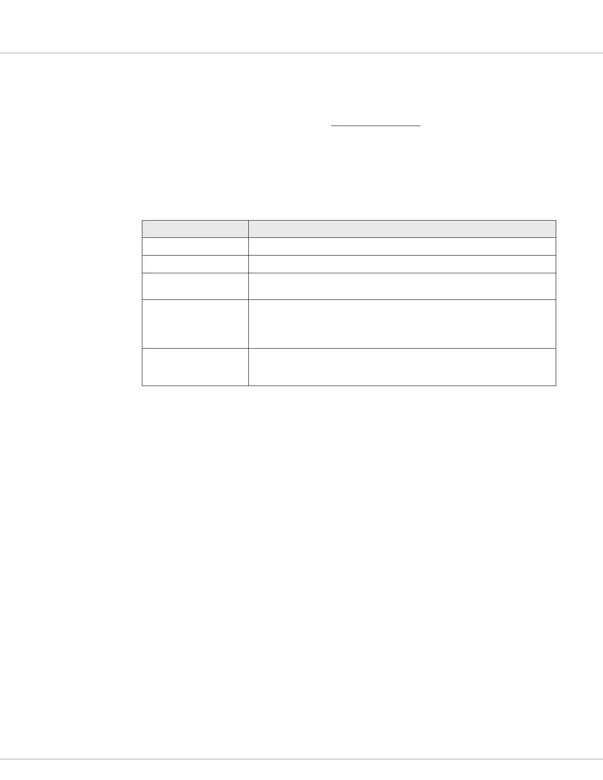
Summary of LED Display Formats
e two LEDs have four dierent display modes, indicating the type of information they are providing.
Table 5 Types of LED Display
Display Status
Neither LED illuminated Controller is not powered on; or vehicle has dead battery; or severe damage.
Yellow LED ashing Controller is operating normally.
Yellow and red LEDs both
on solid
Controller is in Flash program mode.
Red LED on solid Internal hardware fault detected by the Supervisor or Primary microprocessor.
Missing or corrupt software. Interrupting a software download may cause
corruption of the software. Cycle KSI to clear. Reload software or replace
controller if necessary.
Red LED and yellow LED
ashing alternately
Controller has detected a fault. 2-digit code ashed by yellow LED identifies the
specific fault; one or two ashes by red LED indicate whether rst or second code
digit will follow.
TROUBLESHOOTING
e troubleshooting chart, Table 6, provides the following information on all the controller faults:
• fault code
• fault name as displayed on the programmer’s LCD
• the eect of the fault
• possible causes of the fault
• fault set conditions
• fault clear conditions.