2 — INSTALLATION AND WIRING
Curtis 1239E-1269E Manual, os 37.0 RevA – May 2021
Return to TOC
pg. 4
2 — INSTALLATION AND WIRING
MOUNTING THE CONTROLLER
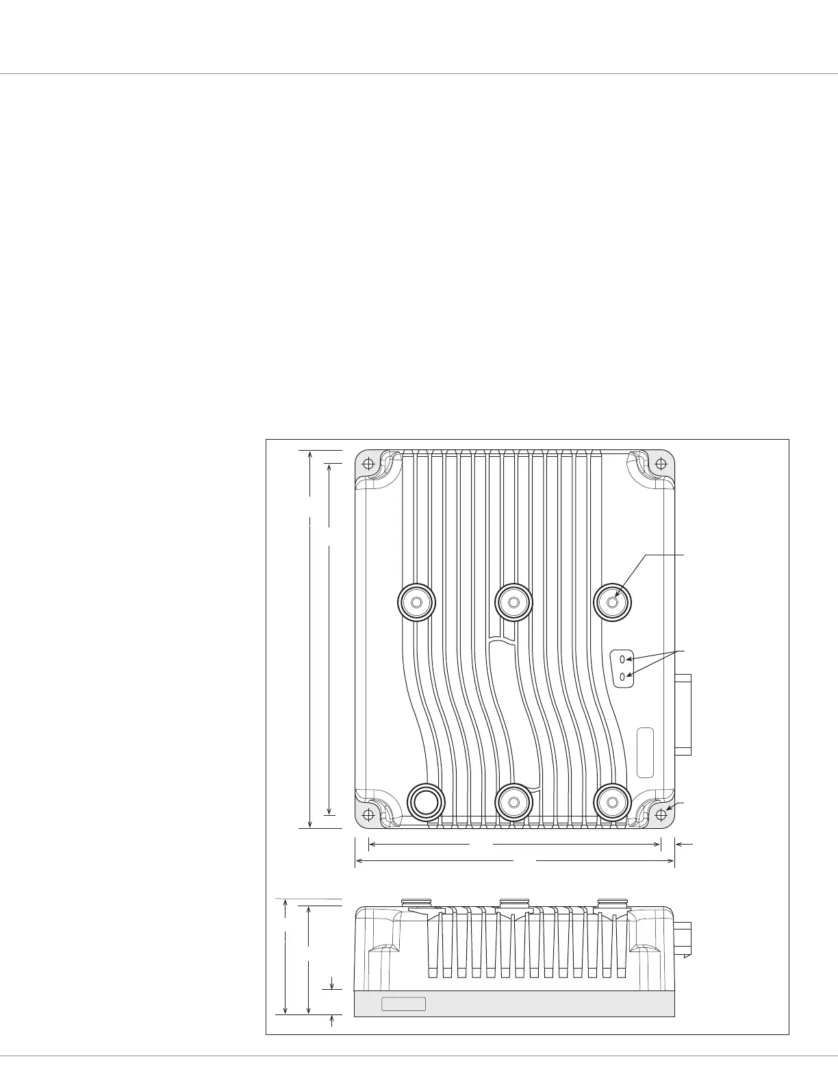
e outline and mounting hole dimensions for the 1239E controller are shown in Figure 3. Figure 4 is
the 1269E. When an Ampseal plug housing is mated with the 35-pin logic receptacle, these controllers
meet the IP65 requirements for environmental protection against dust and water. Nevertheless, in
order to prevent external corrosion and leakage paths from developing, the mounting location
should be carefully chosen to keep the controller as clean and dry as possible.
Mount the controller to a at surface devoid of protrusions, ridges, or a curvature that can cause damage
or distortion to its heatsink (the base plate). Secure the controller using four 6 mm (1/4") diameter bolts
evenly torqued to the vehicle’s mounting surface. ese controller’s heatsink (bottom surface) have a
typical roughness grade of N8 (ISO 1302), with a atness tolerance of < 5 mm (0.13 per 25 mm). A
thermal joint compound is recommended to improve heat conduction from the controller heatsink to
the vehicle’s mounting surface. Typically, when properly mounted to a larger metal surface, additional
heat-sinking or fan-cooling is not necessary to meet the application’s peak and continuous current ratings.
B
-
B
+
FUSE
U
V
W
M8 × 1.25,
5 plcs
19
80
85
212
232
10
Status LEDs
7 dia.,
4 plcs
255
275
Figure 3
Mounting dimensions in mm
for the Curtis 1239E motor
controller.