2 — INSTALLATION AND WIRING
Curtis 1239E-1269E Manual, os 37.0 RevA – May 2021
Return to TOC
pg. 8
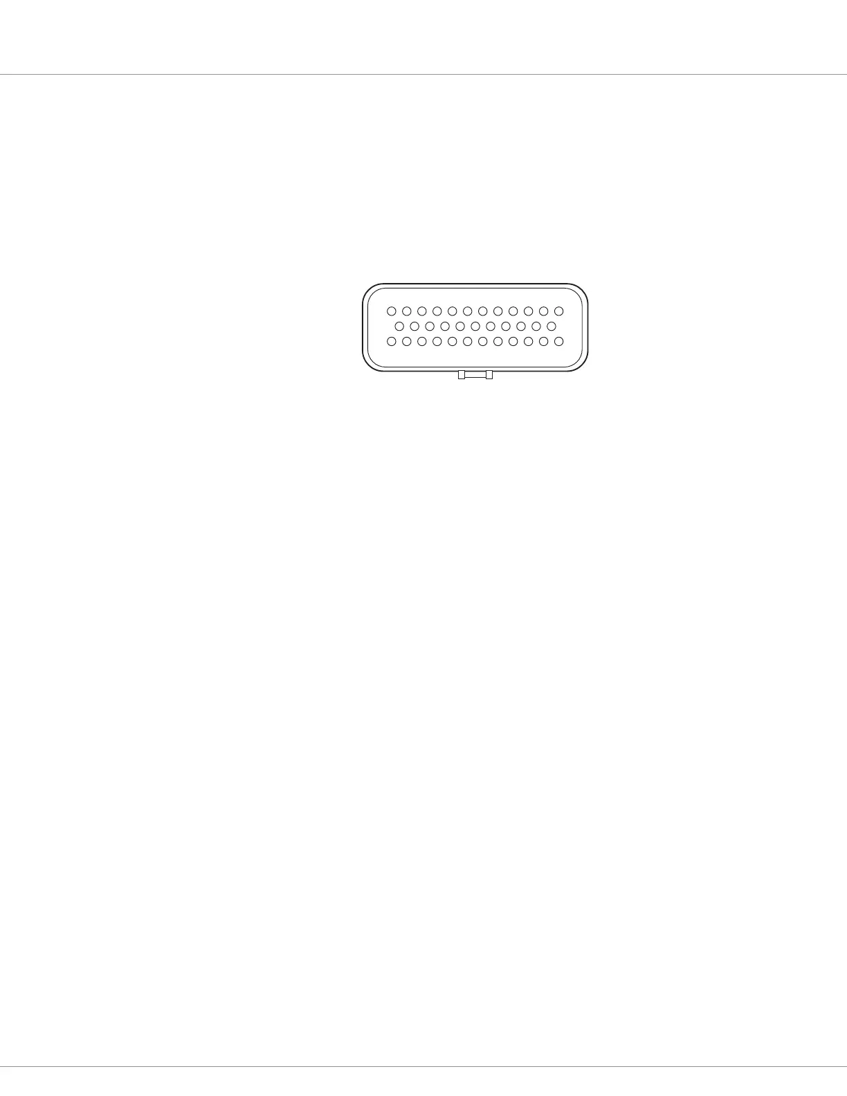
LOW POWER 35-PIN CONNECTIONS
e low power circuit is electrically isolated internally from the high power circuit. All low power
connections are made through a single 35-pin AMPSEAL connector. e mating plug housing is
AMP p/n 776164-1 and the gold-plated socket terminals are AMP p/n 770520-3 (Strip form) and
770854-3 (loose piece). e connector will accept 0.5 – 1.25 mm (20 – 16 AWG) wire with a 1.7 – 2.7
mm diameter (thin-wall insulation). Seal any non-used connector positions that have the silo-
diaphragm pierced with seal plug 770678-1.
e 35 individual pins are characterized in Table 2.
Low Power Wiring Guidelines
Position Feedback (Pins 7, 26, 31, 32)
All four wires (+5V, Feedback A, Feedback B, and I/O ground) should be bundled together as they
run between the motor and controller logic connector. ese can oen be run with the rest of the low
power wiring harness. e encoder cables should not be run near the motor cables. In applications
where this is necessary, shielded cable should be used with the ground shield connected to the low
power ground (pin 7) at only the controller side. In extreme applications, common mode lters (e.g.
ferrite beads) could be used.
CANbus (Pins 21, 23, 34, 35)
It is recommended that the CAN wires be run as a twisted pair. However, many successful applications
at 125 kbit/s are run without twisting, simply using two lines bundled in with the rest of the low
power wiring. e CANbus wiring should be kept away from the high power cables and cross them
at right angles when necessary.
HVIL
HVIL (1269E)
e 1269E has the 2-pin HVIL connection utilizing integral switches on the power connectors.
When the connectors are connected, the switches are closes. When any of the connectors are
disconnected, that switch opens. e switches are connected in series, thus the continuity between
the HVIL pins 1 and 2 is lost. e usage if the HVIL connection is based upon application. Route
the wires with the other low power wiring.
All Other Low Power Wiring
e remaining low power wiring should be run according to standard practices. When designing
the vehicle’s wiring and routing, keep the input lines such as throttle, brake, temperature, and the
above mentioned encoder signals separate from controller’s output lines such as the coil driver
outputs. Avoid routing the low-power wiring parallel to the high power (and current) battery and
motor cables.
13
24
1
23
35
12
J1
harness wire-side view