Return to TOC Curtis 1239E-1269E Manual, os 37.0 RevA – May 2021
10 — VEHICLE CONTROL LANGUAGE (VCL)
pg. 115
INTERFACING THE PROPORTIONAL CURRENT DRIVER
Note: e 1239E and 1269E applications typically do not utilize the proportional current drivers as
used in material handling trucks. See the 1232E-1238E manual (53096) for the parameters. Contact
Curtis to enable these parameters, which will require a dierent OS parameter block.
VCL code can directly interface the proportional current driver (PD), as shown in Figure 20. VCL
can change the working parameters of the PD and can provide the command.
NOTE: Proportional Drivers are not typically used with the 1239E/1269E controller. If the application
calls for proportional drivers, contact the Curtis distributor or the Curtis sales-support oce for
technical assistance.
Depending on how the PD system is to be used, certain parameters need to be set; they can be set
via the 1313/1314 handheld programmer or via VCL.
1. PD_Enable must be set On for current control, otherwise the PD_Output will be controlled
by the VCL function Put_PWM(PWM5,xxxx), which is voltage control.
2. Hyd_Lower_Enable must be set On to use the throttle input to control lowering in a
hydraulic li/lower system.
3. Hyd_Lower_Enable must be set O to allow using a VCL variable (VCL_PD_rottle) as
the PD command.
Once the PD parameters are set, the PD_rottle variable will be mapped between PD_Min_Current
and PD_Max_Current and sent to the dither function. Note that Mapped_rottle is inverted;
lowering its value (making it more negative) increases the PD_rottle value.
e Dither function adds and subtracts from the current command to the PD based on PD_ Dither_Percent,
at a rate set by PD_Dither_Period. e dithered current command is compared to the present PD_Current
and the error is fed into a PI controller. e feedback gains are set by the parameters PD Kp (proportional
gain) and PD Ki (integral gain).
e output of the PI controller becomes the driver’s pulse width modulation, thus controlling the
average current of the driver. e nal output is the VCL variable PD_Output, which is displayed in
the 1313/1314 Monitor » Inputs menu as PD PWM.
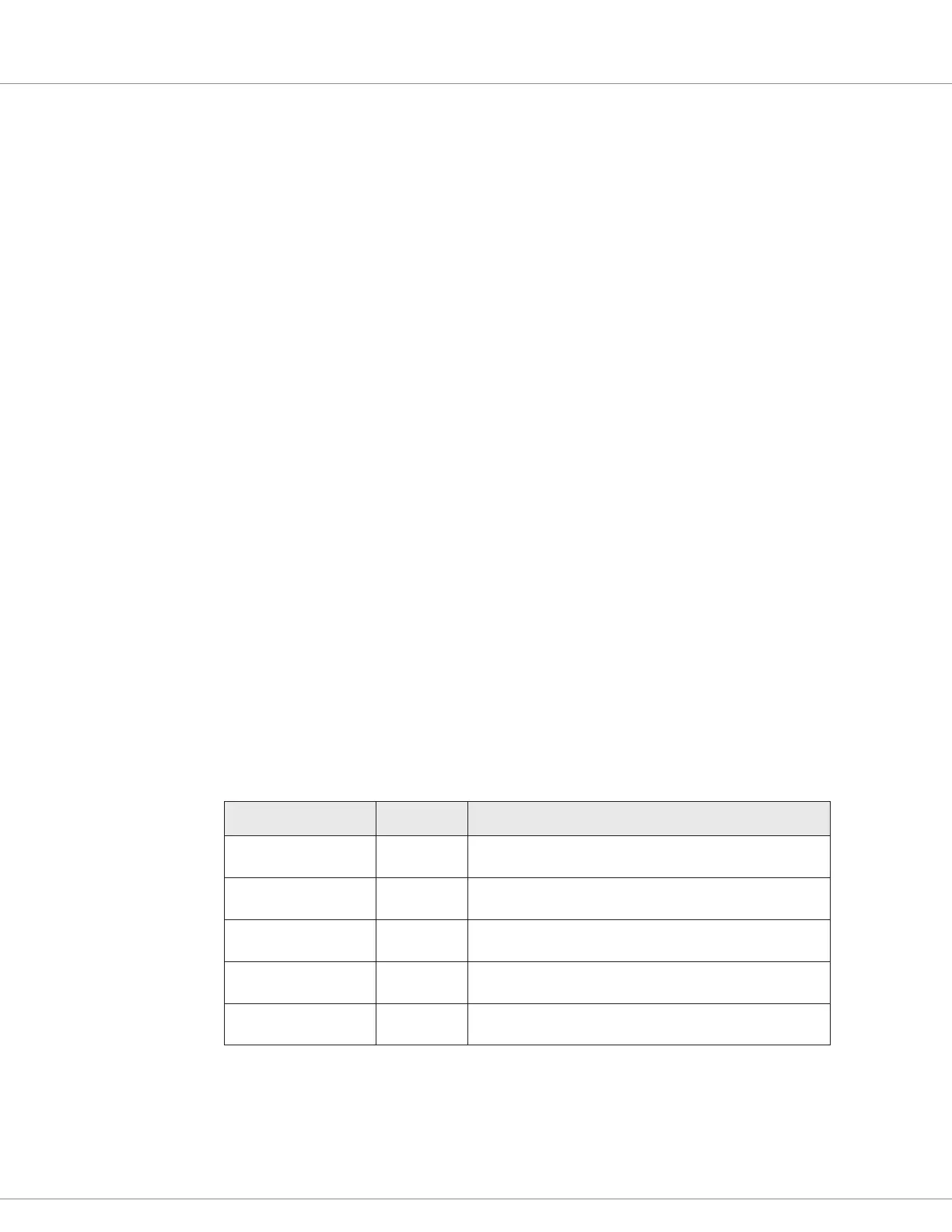
e following PD processing variables are accessible by VCL:
VCL Variable
CAN Object Index
Access Description
Mapped_Throttle
0x3211 0x00
Read Only Command from throttle section.
VCL_PD_Throttle
0x320E 0x00
Read/Write VCL-accessible PD command.
PD_Throttle
0x3210 0x00
Read Only Resultant command to the PD.
PD_Current
0x321C 0x00
Read Only Average current owing in the PD.
PD_Output
0x321E 0x00
Read Only Resultant PWM at PD output.
Quick Link:
Figure 20 p.116