Return to TOC Curtis 1239E-1269E Manual, os 37.0 RevA – May 2021
3 — APPLICATION-SPECIFIC FEATURES
pg. 25
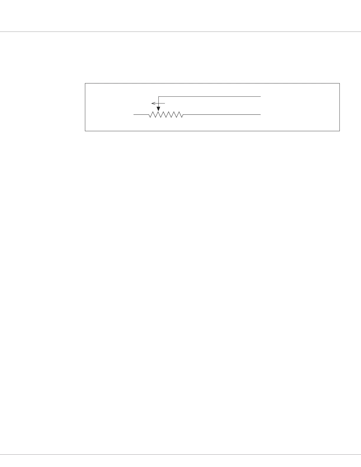
Throttle Type 3
For these 2-wire resistive potentiometers, shown in Figure 9, full throttle request corresponds to
5 kΩ measured between the pot wiper pin and the Pot Low pin.
Broken wire protection is provided by the controller sensing the current ow from the wiper input
(pin 16 or 17) through the potentiometer and into Pot Low (pin 18). For Type 3 throttles, if the Pot
Low input current falls below 0.65 mA, a throttle fault is generated and the throttle request is zeroed.
NOTE: Pot Low (pin 18) must not be tied to either ground (low power ground, pin 7, or B–).
Throttle Type 4
Type 4 throttles operate in wigwag style. No signals to the controller’s forward and reverse inputs
are required; the direction is determined by the wiper input value. Only 0–5V voltage sources and
3-wire potentiometers can be used as Type 4 throttles. e controller interface for Type 4 throttles
is the same as for Type 2 throttles; see Figure 8.
In a Type 4 throttle, the neutral point must be set up somewhere in the center of the throw, with
increasing voltage beyond this point providing increasing forward command and voltages below this
point providing increasing reverse command. For example, to set the Forward Deadband at 2.6V with
Forward Max at 4V, and Reverse Deadband at 2.4V with Reverse Max at 1V.
When a 3-wire pot is used, the controller provides full fault protection. When a voltage throttle
is used, the controller will detect open breaks in the wiper input but cannot provide full throttle
fault protection.
Throttle Type 5
rottle Type 5 provides a dierent way of sending the throttle command to the controller. is
throttle type uses VCL to dene the throttle signal that will be “input” into the throttle signal chain
as VCL_rottle (see Figure 18).
is throttle type can be used for either the drive throttle or the brake throttle by using the VCL
variables VCL_rottle and VCL_Brake. How the VCL program is written will determine the source
of the throttle signal, making this a very exible throttle input method. VCL can be written to use the
throttle pot inputs, switch inputs, or CAN communication messages as the source of the throttle signals.
Setting the rottle Type to Type 5 also allows the throttle pot input (Pin 16) to be redened by a
VCL program for uses other than throttle input.
Note: e option also applies to the Brake Type, which when set to Type 5 uses VCL_Brake as signal
chain for the Brake_Command (see the Brake parameter menu and Figure 18).
For questions regarding this throttle type, contact the Curtis distributor or support engineer.
Pot Low input (Pin 18)
Pot Wiper input (Pin 16 or 17)
0–5kΩ
FASTER
Figure 9
Wiring for Type 3
throttles.
Quick Links:
Figure 18 p.112
rottle Type parameter p.49
Brake Type parameter p.51