6
Curtis 1244 Manual, Rev. E
CONNECTIONS
Low Current Connections
ree low current connectors are built into the 1244 controller. ey are located
in a row on the top of the controller:
Pin 1 keyswitch input (KSI)
Pin 2 interlock input
Pin 3 Mode Select 1 input
Pin 4 Mode Select 2 input
Pin 5 Fault 1 output
Pin 6 Fault 2 output
Pin 7 emergency reverse input
Pin 8 pedal switch input
Pin 9 coil return input
Pin 10 forward input
Pin 11 reverse input
Pin 12 hour meter enable output
Pin 13 throttle: 3-wire pot high
Pin 14 throttle: pot low
Pin 15 throttle: 3-wire pot wiper or 0–5V
Pin 16 throttle: 2-wire 5kΩ–0 or 0–5kΩ input
Pin 17 main contactor driver output
Pin 18 auxiliary contactor driver output
Pin 19 reverse signal driver output
Pin 20 electromagnetic brake driver output
Pin 21 (not used)
Pin 22 emergency reverse check output
Pin 23 (not used)
Pin 24 (not used)
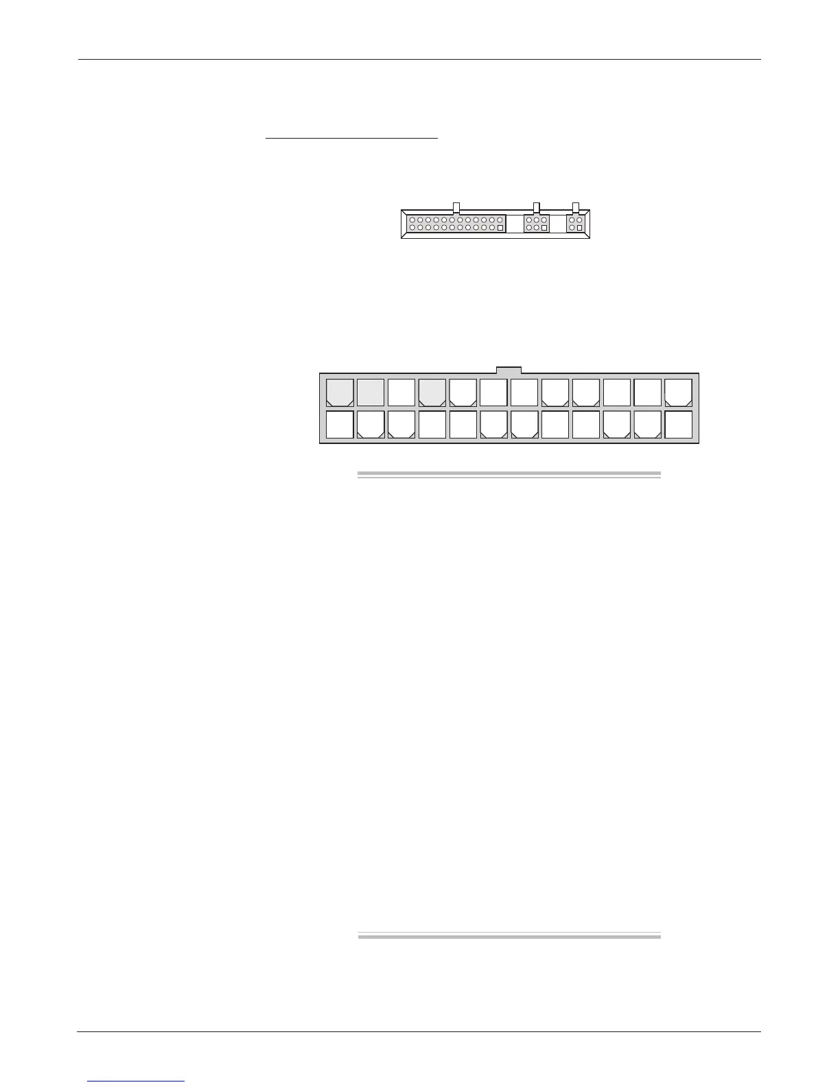
24 23 22 21 20 19 18 17 16 15 14 13
12 11 10 9 8 7 6 5 4 3 2 1
e 24-pin connector provides the logic control connections. e mating
connector is a 24-pin Molex Mini-Fit Jr. connector part number 39-01-2245
using type 5556 terminals.
24-pin 6-pin 4-pin
2 — INSTALLATION & WIRING:
Controller
 Loading...


