Curtis 1244 Manual, Rev. E
43
With the fault code parameter specified “On,” the controller’s fault outputs
will provide information in Fault Code format. With the fault code parameter
specified “O,” the controller’s fault outputs will provide information in Fault
Category format.
In Fault Code format, the two fault lines operate independently. When a
fault is present, the Fault 1 driver (Pin 5) provides a pulsed signal equivalent to
the fault code ashed by the controller’s built-in Status LED. is signal can be
used to drive an LED located on the display panel to provide the fault code in-
formation to an operator, or to any remote panel. e Fault 2 driver (Pin 6) pulls
low (to B-) and remains on until the fault is cleared; it can also be used to drive a
remote LED. When no faults are present, these outputs will both be open (o).
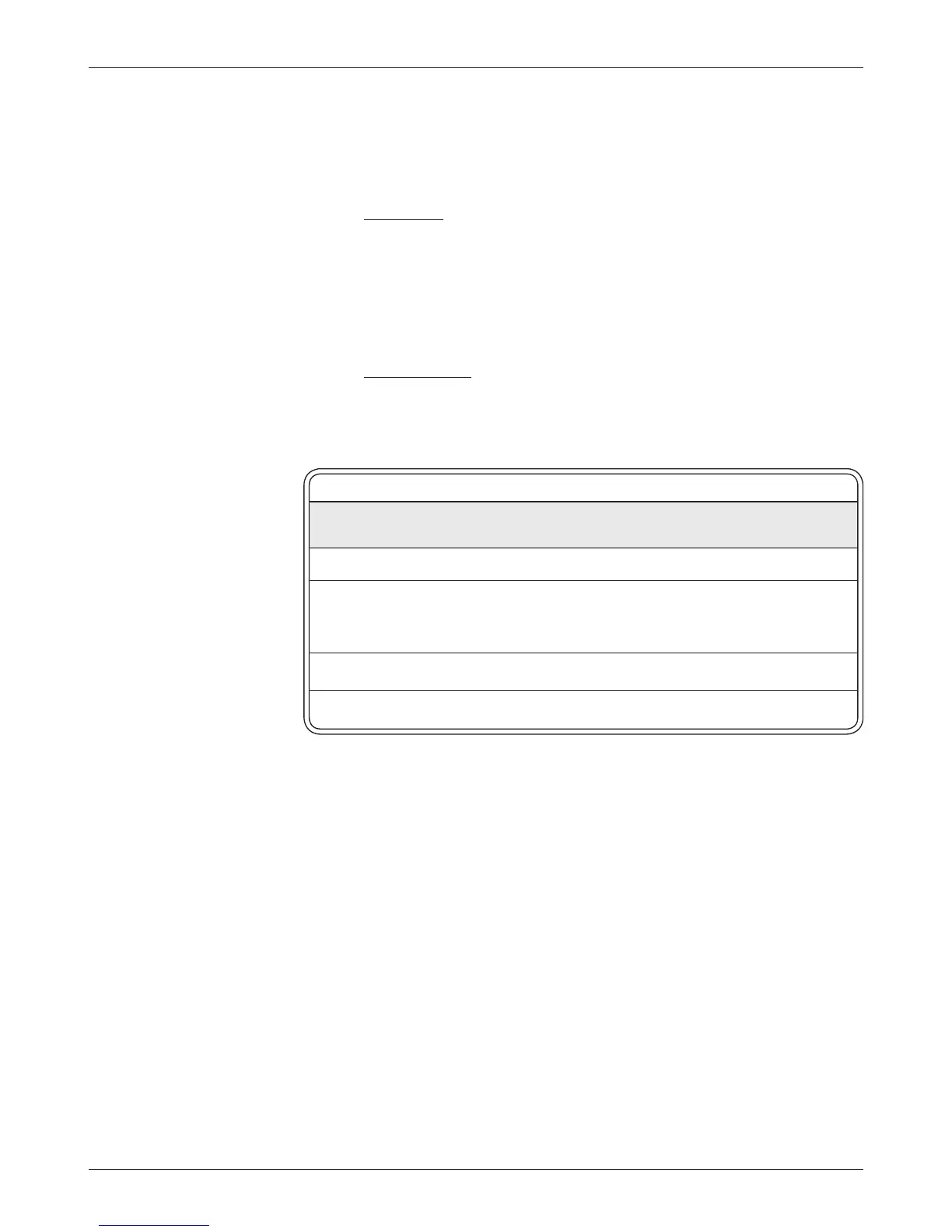
In Fault Category format, the two fault lines together define one of four
fault categories. Table 4 describes the four fault categories, shows the state of
the two outputs for each category, and lists the faults that might be present
when each of the four fault category signals is transmitted.
Table 4 FAULT CATEGORIES
FAULT FAULT 1 FAULT 2
CATEGORY OUTPUT OUTPUT POSSIBLE EXISTING FAULTS
(Pin 5) (Pin 6)
0 HIGH HIGH (no faults present, or controller not operational)
1 LOw HIGH HW Failsafe; M-, Current Sensor, or Motor Fault;
Throttle Fault; Emergency Reverse Wiring Fault;
Contactor or Output Driver Fault; Precharge Fault
2 HIGH LOw Low Battery Voltage; Overvoltage; Thermal Cutback
3 LOw LOw HPD; SRO; Anti-Tiedown
MAIN CONT INTR
e main contactor driver interlock parameter allows the manufacturer to
define a dual switch requirement to operate the vehicle. When this parameter
is set to “On,” the controller requires that both the KSI input (Pin 1) and the
interlock input (Pin 2) be pulled high (to B+) before the controller will engage
the main contactor. e main contactor will open after the interlock switch is
opened and the sequencing and main open delays expire. If this parameter is set
to “O,” only the KSI input is required for the main contactor to be engaged.
MAIN OPEN DLy
e main contactor dropout delay parameter is applicable only if the main
contactor driver interlock parameter has been set to “On.” e dropout delay
3 — PROGRAMMABLE PARAMETERS: Output Driver Parameters
Output Driver Parameters
 Loading...


