34
Curtis 1244 Manual, Rev. E
3 — PROGRAMMABLE PARAMETERS: Throttle Parameters
M1–M4, ThRTL MAP
e throttle map parameter modifies the vehicle’s response to the throttle input.
is parameter determines the controller output, based on the selected throttle
control mode, for a given amount of applied throttle. Setting the throttle map
parameter at 50% provides a linear output response to throttle position. Values
below 50% reduce the controller output at low throttle settings, providing en-
hanced slow speed control. Values above 50% give the vehicle a faster, jumpier
feel at low throttle settings.
e throttle map can be programmed in 5% increments between 20%
and 80%. e number refers to the controller output at half throttle, as a
percentage of the throttle’s full active range. e throttle’s active range is the
voltage or resistance between the 0% output point (throttle deadband) and the
100% output point (throttle max). For example, if maximum speed is set at
100% and creep speed is set at 0, a throttle map setting of 50% will give 50%
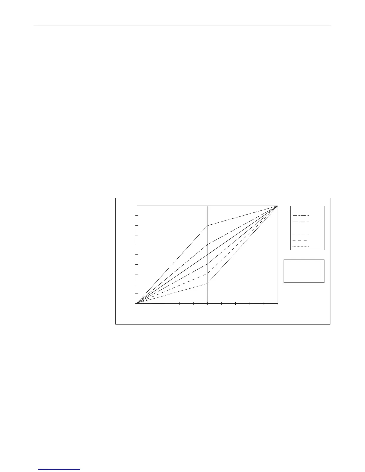
output at half throttle. e 50% setting corresponds to a linear response. Six
throttle map profiles (20, 30, 40, 50, 60, and 80%) are shown as examples in
Figure 16, with the maximum speed set at 100% and the creep speed set 0.
Fig. 16 rottle maps for
controller with maximum
speed set at 100% and
creep speed set at 0.
Lowering the max speed or raising the creep speed limits the controller’s
output range. rottle map profiles with the creep speed raised from zero to
10% and the max speed reduced from 100% to 80% are shown in Figure 17.
e throttle map is always a percentage of the controller’s output range. So, in
these examples, the throttle map is a percentage of the 10–80% output range;
a 40% throttle map setting will give 38% output at half throttle (40% of the
70% range, which is 28%, shifted up to 38% because it starts at the 10%
creep speed). Controller output will begin to increase above the set creep speed
as soon as the throttle is rotated out of its normal neutral range (deadband).
Controller output will continue to increase, following the curve defined by the
THROTTLE INPUT (percent of active range)
80%
60%
50%
40%
30%
20%
THROTTLE MAP
100
90
80
70
60
50
40
30
20
10
0
100908070605040302010 0
SPEED PARAMETERS
0% Creep Speed
100% Max Speed
CONTROLLER OUTPUT (PWM percent)
 Loading...


