Curtis 1244 Manual, Rev. E
33
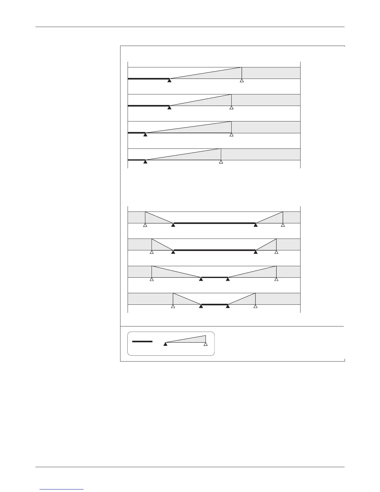
Fig. 15, cont’d
Eect of adjusting the
throttle max parameter
(rottle Types 3 and 4).
3 — PROGRAMMABLE PARAMETERS: Throttle Parameters
e programmer displays the throttle max parameter as a percentage of
the active throttle voltage range. e throttle max parameter can be adjusted
from 100% to 60%, in 2% increments. e nominal throttle wiper voltage
range depends on the throttle type selected. See Table 1 (page 10) for the char-
acteristics of your selected throttle type.
0–5kΩ Throttle: Type 3
0–5V Single-Ended Throttle: Type 2
5kΩ–0 Throttle: Type 1
0–5V Wigwag Throttle: Type 4
0
5V
1.2V
(1.4kΩ)
3.3V
(5.0kΩ)
100% Throttle Max
30% Deadband
0.5V
(400Ω)
2.7V
(3.9kΩ)
3.0V
(4.5kΩ)
90% Throttle Max
30% Deadband
90% Throttle Max
10% Deadband
60% Throttle Max
10% Deadband
Notes: Voltages shown are at the pot wiper relative to B-.
For throttle types 1 and 3, the deadband points are
defined in terms of the nominal 5kΩ pot resistance.
Using a pot of greater or lesser resistance will give
different values for the deadband points.
KEY
100%
Throttle
Deadband
Controller
Output
0%
0
5V
2.0V
100% Throttle Max
30% Deadband
0.2V
4.5V
0.2V
3.0V
2.0V
4.5V
90% Throttle Max
30% Deadband
90% Throttle Max
10% Deadband
60% Throttle Max
10% Deadband
0
5V
2.3V
(3.2kΩ)
0.2V
(0Ω)
100% Throttle Max
30% Deadband
3.0V
(4.5kΩ)
1.7V
(2.2kΩ)
0.6V
(450Ω)
90% Throttle Max
30% Deadband
90% Throttle Max
10% Deadband
60% Throttle Max
10% Deadband
0.6V
(450Ω)
2.3V
(3.2kΩ)
3.0V
(4.5kΩ)
1.2V
(1.4kΩ)
0.5V
(400Ω)
3.0V
(4.5kΩ)
0
5V
100% Throttle Max
30% Deadband
90% Throttle Max
30% Deadband
90% Throttle Max
10% Deadband
60% Throttle Max
10% Deadband
3.7V
(3.7kΩ)
4.5V
(4.5kΩ)
0.5V
(500Ω)
1.3V
(1.3kΩ)
3.7V
(3.7kΩ)
4.3V
(4.3kΩ)
0.7V
(700Ω)
1.3V
1.3kΩ)
2.9V
(2.9kΩ)
4.3V
(4.3kΩ)
0.7V
(700Ω)
2.1V
(2.1kΩ)
2.9V
(2.9kΩ)
3.7V
(3.7kΩ)
1.3V
(1.3kΩ)
2.1V
(2.1kΩ)
 Loading...


