8
Curtis 1244 Manual, Rev. E
2 — INSTALLATION & WIRING: Controller
WIRING: Standard Conguration
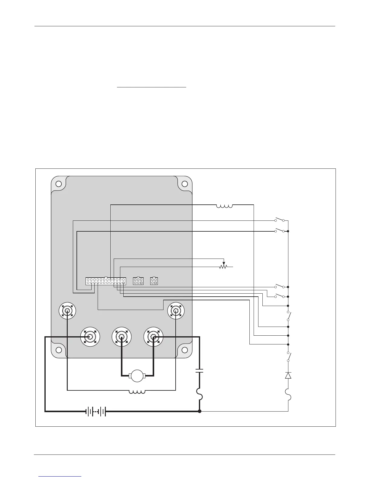
Figure 3 shows the typical wiring configuration for most applications. e
interlock switch is typically a seat switch, tiller switch, or foot switch.
Standard Power Wiring
Motor armature winding is straightforward, with the armature’s A1 connection
going to the controller’s B+ bus bar and the armature’s A2 connection going
to the controller’s M- bus bar.
e motor’s field connections (
F1 and F2) to the controller are less ob-
vious. e direction of vehicle travel with the forward direction selected will
depend on how the
F1 and F2 connections are made to the controller’s two field
terminals and how the motor shaft is connected to the drive wheels through
the vehicle’s drive train.
Fig. 3 Standard wiring configuration, Curtis 1244 controller.
B- B+M-
F2F1
INTERLOCK
5 kΩ–0 THROTTLE
(TYPICAL)
FORWARD
MAIN
CONTACTOR
COIL
POLARITY
PROTECTION
DIODE
REVERSE
MODE SELECT 2
MODE SELECT 1
B+
B-
KEYSWITCH
POWER
FUSE
A
MAIN
CONTACTOR
A2 A1
F1 F2
CONTROL
FUSE
 Loading...


