Curtis 1244 Manual, Rev. E
9
2 — INSTALLATION & WIRING: Controller
Standard Control Wiring
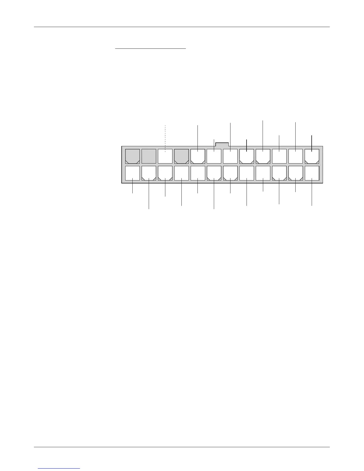
Wiring for the input switches and contactors is shown in Figure 3; the connector
is shown in more detail below.
e main contactor coil must be wired directly to the controller as shown in
Figure 3. e controller can be programmed to check for welded or missing
main contactor faults and uses the main contactor coil driver output to remove
power from the controller and motor in the event of various other faults. If the
main contactor coil is not wired to Pin 17, the controller will not be able
to open the main contactor in serious fault conditions and the system will
therefore not meet EEC safety requirements.
12 11 10 9 8 7 6 5 4 3 2 1
24 23 22 21 20 19 18 17 16 15 14 13
INTERLOCK
ELECTRO-
MAGNETIC
BRAKE
DRIVER
REVERSE
SIGNAL
DRIVER
EMERGENCY
REVERSE
CHECK
(factory option)
FAULT
2
FAULT
1
HOUR
METER
REVERSE
24-pin detail (see Fig. 3):
EMERGENCY
REVERSE
(walkies only)
AUX
CONTACTOR
DRIVER
MAIN
CONTACTOR
DRIVER
POT
WIPER
POT
HIGH
POT
LOW
2-WIRE
POT
(5 kΩ)
PEDAL
SWITCH
KEYSWITCH
INPUT (KSI)
FORWARD
MODE
SELECT
2
MODE
SELECT
1
COIL
RETURN
 Loading...


