16
Curtis 1244 Manual, Rev. E
2 — INSTALLATION & WIRING: Fault Outputs and Contactor Drivers
CAN-Nodes Throttle (“Type 5”)
e “Type 5” throttle option is designed for use with CAN-based control
systems. No connections are required to the throttle input pins (Pins 13–16)
or direction pins (Pins 10 and 11), because all communications are handled
through the 6-pin CAN-Nodes interface connector. Details on how to combine
a given throttle with the CAN-Nodes system are provided in the Curtis CAN
Protocol Document. Fault detection for Type 5 throttles is handled by the
CAN CRC (Cyclic Redundancy Check) function, which is part of each node
in the CAN Bus architecture.
WIRING: Fault Outputs
e 1244 controller has two fault output drivers, at Pin 5 and Pin 6, which
can be used to provide diagnostic information either to a display panel on the
vehicle or to a remote location. ese outputs are rated at 10mA maximum
current at the nominal battery pack voltage. For information on programming
these outputs, see Section 3: Programmable Parameters.
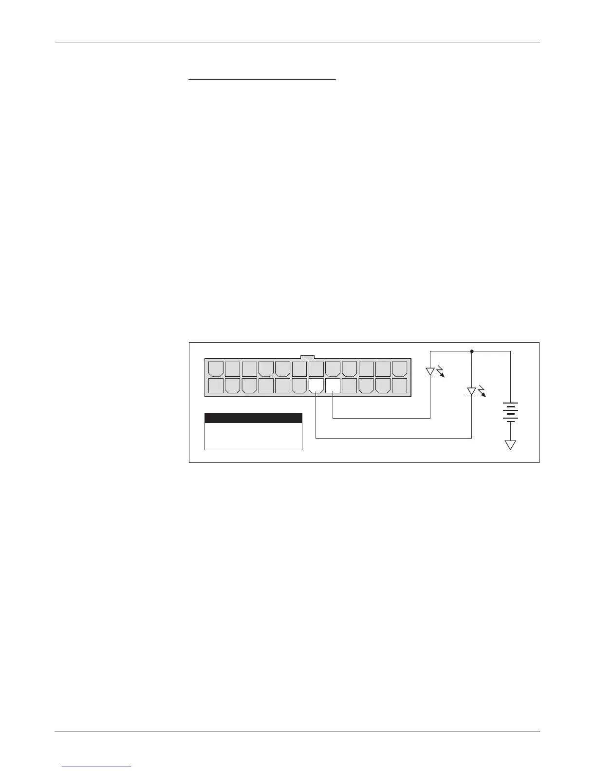
Wiring for the Fault 1 and Fault 2 outputs is shown in Figure 11.
Fig. 11 Wiring for fault
outputs.
Fault 1
Pin 6
Pin 5
Fault 2 Output
Fault 1 Output
PIN KEY
Fault 2
14 1315161718192021222324
12 11 10 9 8 7 6 5 4 3 2 1
+
B-
-
WIRING: Contactor Drivers
e 1244 controller provides contactor coil drivers (at Pins 17–20) for the
main contactor, auxiliary contactor, reverse signal, and electromagnetic brake
functions. ese four outputs are low side drivers, designed to energize contactor
coils. e auxiliary, reverse signal, and electromagnetic brake drivers are optional
functions. ey are available only if the Accessory Driver option is specified—see
Section 4, page 50.
It is not necessary to specify the contactors’ coil voltage at the nominal
battery pack voltage as long as the Contactor Pull-In Voltage and Contactor
Holding Voltage parameters are programmed to accommodate the coils’ volt-
age rating. However, all coil voltage ratings should be the same, since only one
value of pull-in and holding voltage can be specified for all four of the drivers.
e driver outputs are rated at 2 amps and overcurrent protected at
3amps. e controller can be programmed to check for missing coil faults.
 Loading...


