4
Curtis 1228 Manual, Rev. F
INSTALLATION AND WIRING
MOUNTING THE CONTROLLER
The 1228 controller can be oriented in any position, but the location should
be carefully chosen to keep the controller clean and dry. If a clean, dry
mounting location cannot be found, a cover must be used to shield the
controller from water and contaminants.
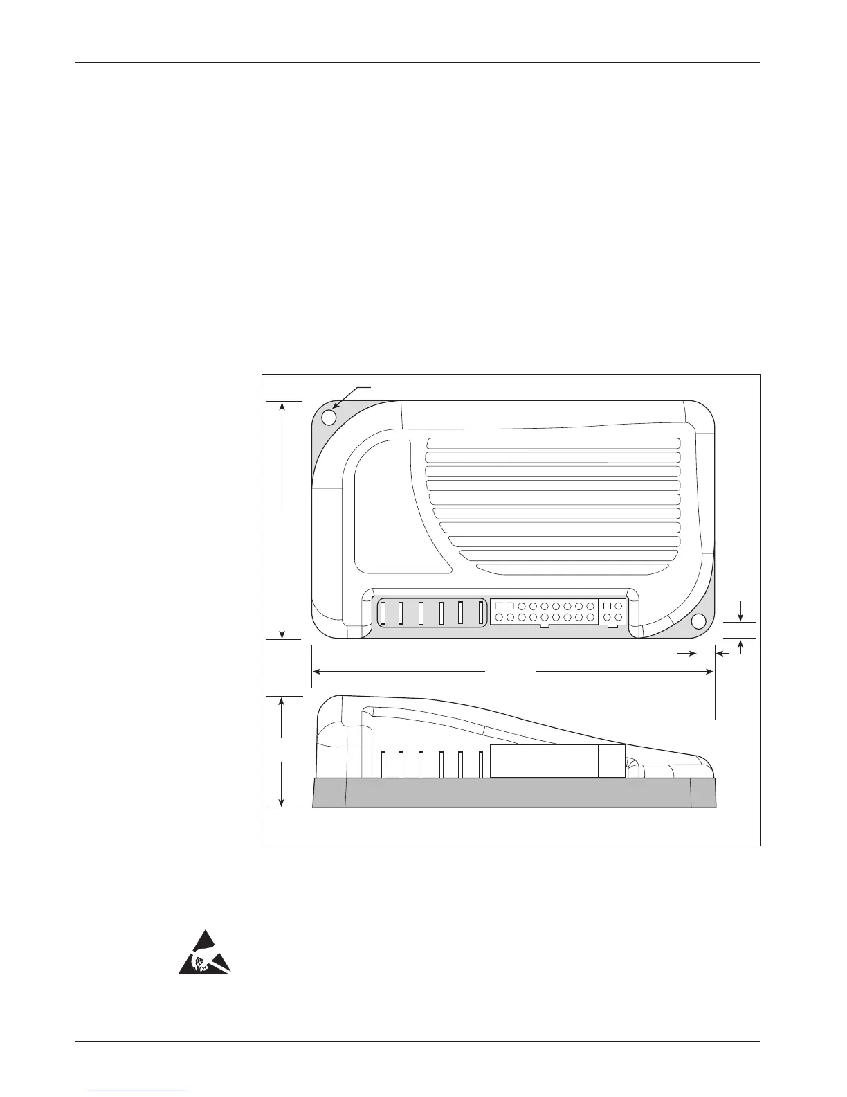
The outline and mounting hole dimensions are shown in Figure 2. The
controller should be mounted by means of the two mounting holes at the op
-
posing corners of the heatsink, using M4
× 20 mm (#8 × 0.75") screws.
This will give 6 mm (0.25") of exposed screw, which can be increased according
to the thickness of the mounting site.
2
2 — INSTALLATION & WIRING
Fig. 2 Mounting
dimensions, Curtis 1228
controller.
Dimensions in millimeters and (inches)
B+ B- M2 M1 LOGIC PROG
4.8 (0.19) dia., 2 plcs
156 (6.13)
6.8 (0.27)
6.8
(0.27)
43
(1.71)
91
(3.60)
You will need to take steps during the design and development of your
end product to ensure that its EMC performance complies with applicable
regulations; suggestions are presented in Appendix A.
The 1228 controller contains ESD-sensitive components. Use appro-
priate precautions in connecting, disconnecting, and handling the controller.
See installation suggestions in Appendix A for protecting the controller from
ESD damage.
✭