Curtis 1228 Manual, Rev. F
13
brake will not release when the vehicle stops. Also, the controller must be con-
nected to the batteries and the keyswitch must be turned on in order for the
push feature to be used.
Brake Release Switch (Brake Coil Disable Switch)
If a brake release lever is used to release the electromagnetic brake mechanically,
a brake coil disable switch is recommended. This switch opens the electromag
-
netic brake coil circuit when the mechanical brake release lever releases the
brake from the motor shaft. The open brake coil circuit will register as a fault,
inhibiting controller operation if an operator attempts to drive the vehicle with
the brake mechanically released. This safety feature ensures that the vehicle
cannot be driven when the brake cannot be engaged.
Inhibit
The inhibit input can be used to inhibit operation during battery charging. The
inhibit input overrides all other controller inputs and is active when low (i.e.,
when shorted to B-). The input can be left floating when not engaged; it does
not need to be pulled high. Typically, battery chargers have a dedicated third
terminal that automatically provides inhibit. If your battery charger does not
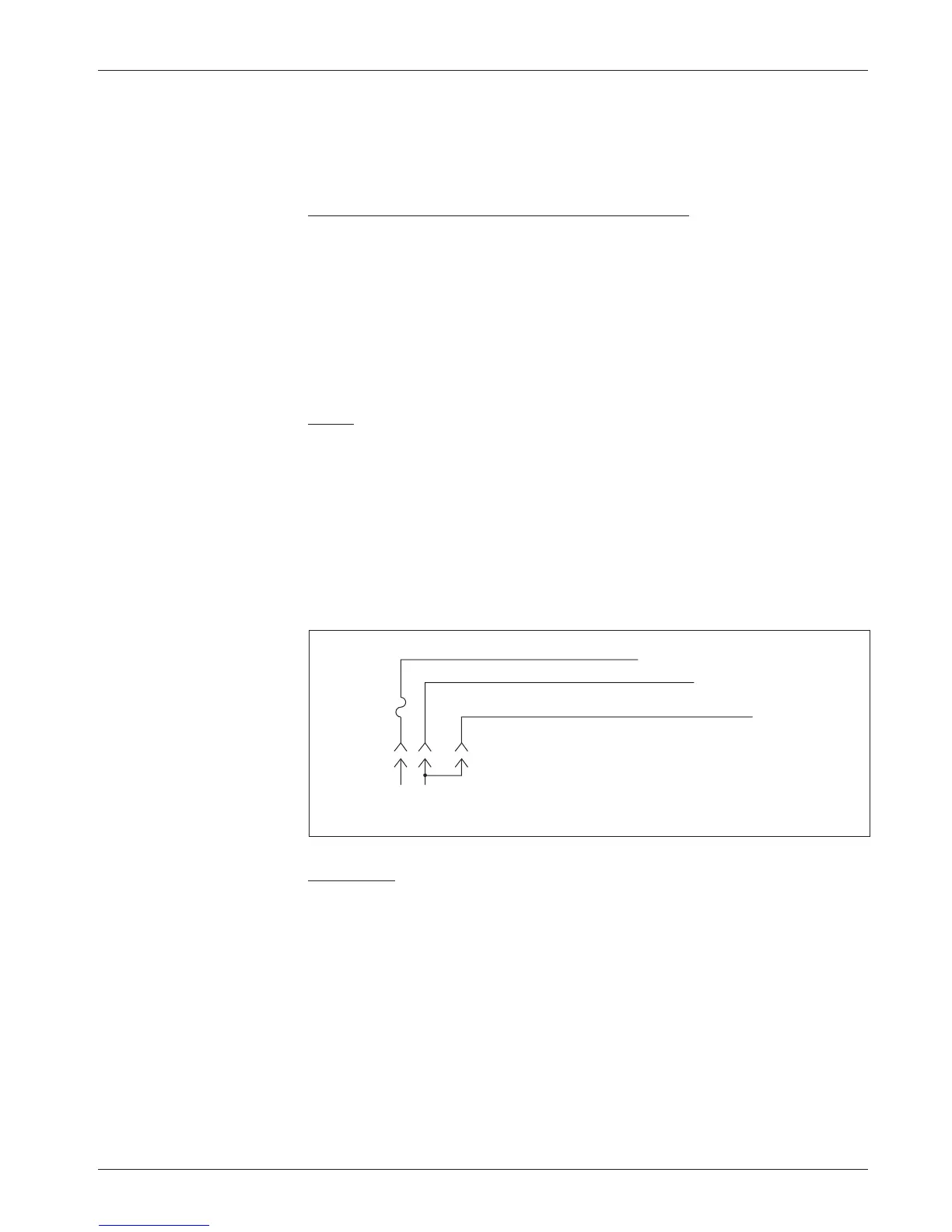
have this third terminal, inhibit can be wired as shown in Figure 8.
The battery charger should only be connected after the vehicle has come
to a complete stop.
Fig. 8 Wiring to inhibit
operation during battery
charging (for battery
chargers without a
dedicated inhibit
terminal).
BATTERY
CHARGER
+ -
CONTROL
FUSE
B+ (Pin 10 or 11)
B- (Pin 1 or 2)
Inhibit input (Pin 12)
Status LED
The 1228 controller has the capability to drive a panel indicator LED, which
can be used to tell the operator, at a glance, the controller’s status. This LED
always indicates whether the controller is powered on or off. The status LED
will also provide diagnostics information via flash codes (see Section 7).
If a status LED is used, it should be installed with the proper resistor
in series. The controller’s LED driver is capable of a maximum current of 15
mA. The recommended resistor—designed to limit driver current to 15 mA
when active—is 2.4 k
Ω, 0.5 W. Alternatively, an LED with a built-in resistor
can be used; it should be rated for 24V or 36V operation, depending on the
controller model.
2 — INSTALLATION & WIRING: Switches, etc.