8
Curtis 1228 Manual, Rev. F
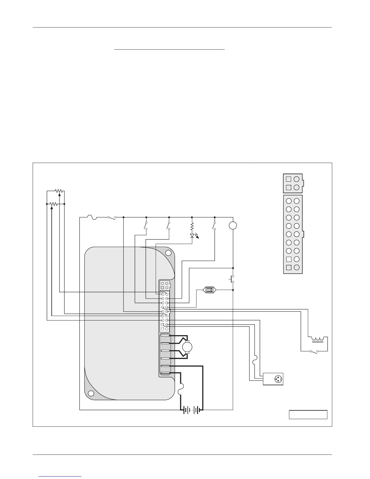
Fig. 4a Standard wiring configuration, Curtis 1228 controller, in applications with no seat lift.
R
2.4 kΩ, 0.5 W
J9
J10
B+
B-
A
R
H
1
2
3
4
INHIBIT
BRAKE
MODE
(M1, M2)
HORN
SPEED
LIMIT
POT
(100 kΩ)
PUSH
5 kΩ POT
THROTTLE
REVERSE
optional switch
operated by
mechanical
brake release
CONTROL
FUSE
KEY
SWITCH
TRACTION
MOTOR
POWER
FUSE
BDI
BATTERIES
BATTERY
CHARGER
CONNECTOR
STATUS
LED
SPEED POT
REVERSE
HORN
BDI
BRAKE
+
POT LO
W
INHIBI
T
B+
B+
STATUS
MODE (M1, M2)
PUSH
BRAKE
-
KSI
POT WIPER
POT HIGH
B-
B-
16
13
14
10
17
18
11
12
15
7
4
5
1
8
9
2
3
6
Connector detail:
+15V
Tx DATA
GROUND
Rx DATA
B+
2 — INSTALLATION & WIRING
Applications without Seat Lift Feature
The wiring presented in Figures 4a and 4b is the same as in Figures 3a and
3b, except the components and wiring used to implement the seat lift feature
have been removed. This simpler configuration is applicable to vehicles such
as sweepers/scrubbers and scooters that do not have seat lift motors.
This installation includes a single-ended, 3-wire 5k
Ω potentiometer
throttle, which is used with a reverse switch. With a wigwag throttle, a reverse
switch is not used and Pin 17 is left unconnected.
In this example, one set of B+/B- pins is left unused because the logic
circuit is wired directly to the vehicle’s battery pack.
Note: When using the B+ pins (10, 11) an appropriately sized fuse must
be added to the circuit to avoid damage to the controller.