Curtis 1228 Manual, Rev. F
7
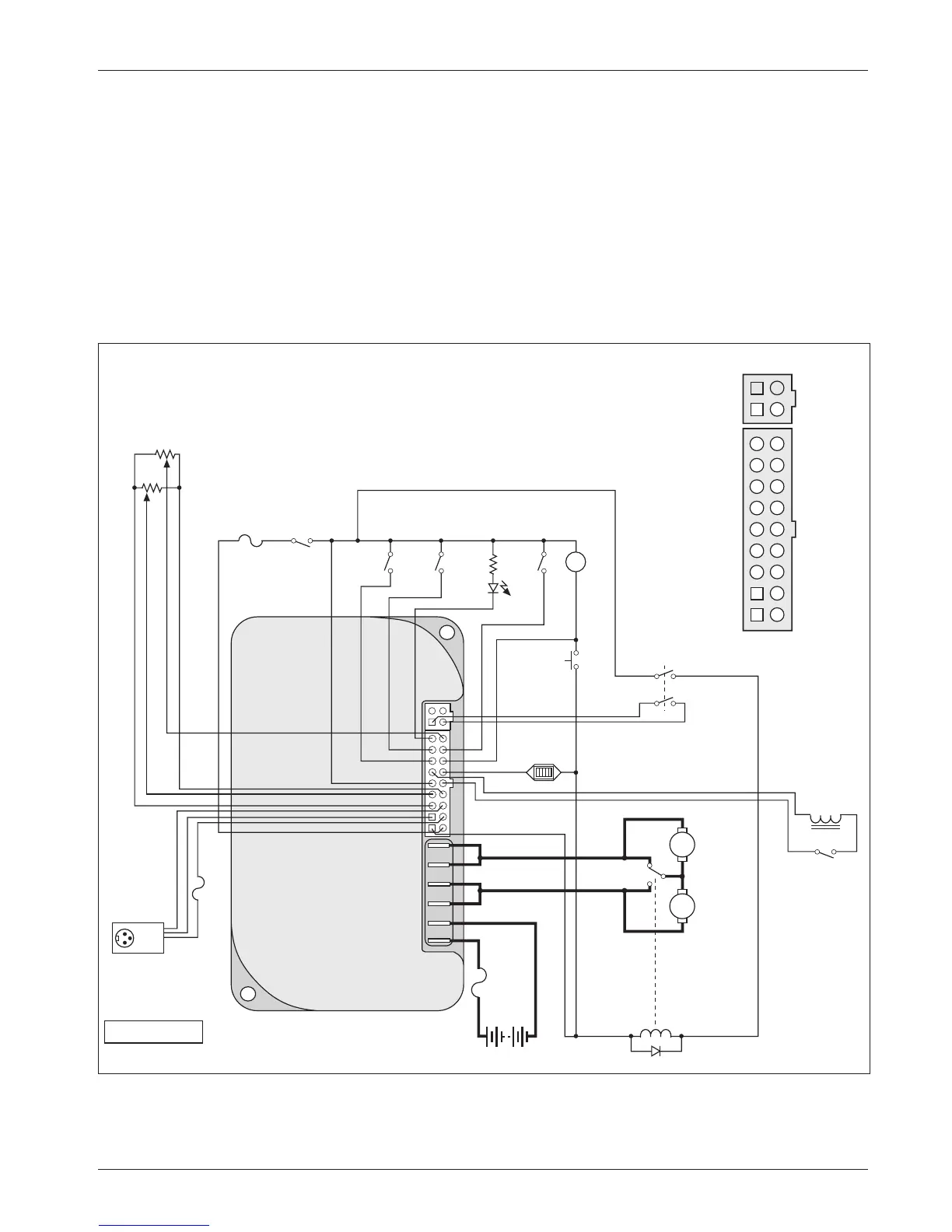
The wiring diagram presented in Figure 3b illustrates an alternative
wiring that can be used in some applications. Here the control circuit is con-
nected to the B+ and B- pins (in this example, Pins 1 and 10) instead of to the
battery pack. All four of the B+ and B- pins (Pins 1, 2, 10, 11) are connected
internally to the controller’s
B+, B- terminals. The pins are rated at 9 amps, so
this configuration is appropriate only for applications where accessory power
drawn from these pins will never exceed 9 amps.
Note: When using the B+ pins (10, 11) an appropriately sized fuse must
be added to the circuit to avoid damage to the controller.
2 — INSTALLATION & WIRING
Fig. 3b Alternative wiring configuration, for low keyswitch current (≤ 9 A) applications.
R
2.4 kΩ, 0.5 W
1
2
3
4
J10
J9
B+
B-
A
R
H
A
INHIBIT
BRAKE
MODE
(M1, M2)
HORN
SPEED
LIMIT
POT
(100 kΩ)
PUSH
5 k
Ω
POT
THROTTL
E
REVERSE
optional switch
operated by
mechanical
brake release
CONTROL
FUSE
KEY
SWITCH
SEAT LIF
T
MOTOR
POWER
FUSE
BDI
BATTERIES
BATTERY
CHARGER
CONNECTOR
STATUS
LED
Connector detail:
SPEED POT
REVERSE
HORN
BDI
BRAKE
+
POT LO
W
INHIBI
T
B+
B+
STATUS
MODE (M1, M2)
PUSH
BRAKE -
KSI
POT WIPER
POT HIGH
B-
B-
TRACTION
MOTOR
N.C.
SEAT LIFT
RELAY
SEAT LIFT
SWITCH
+15V
Tx DATA
GROUND
Rx DATA
7
4
5
1
8
9
2
3
6
16
13
14
10
17
18
11
12
15
B+