6
Curtis 1228 Manual, Rev. F
2 — INSTALLATION & WIRING
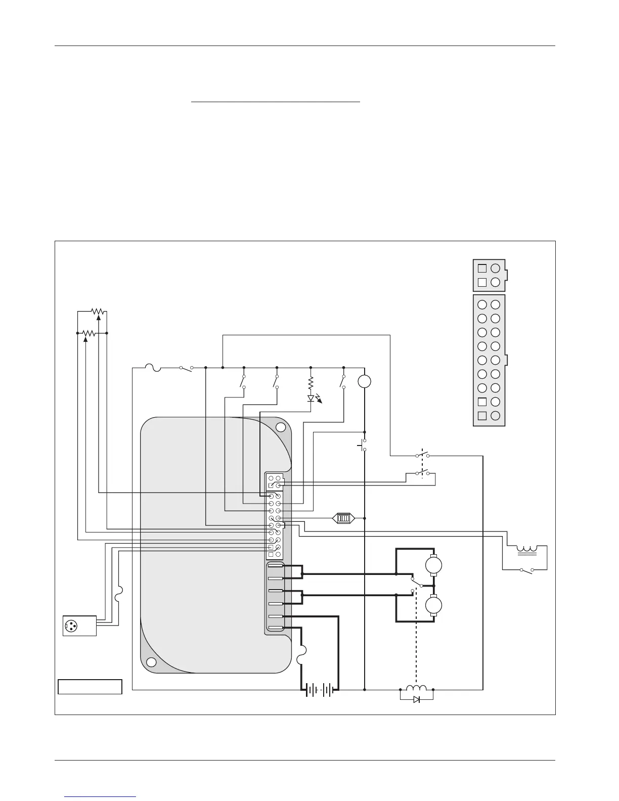
Fig. 3a Standard wiring configuration, Curtis 1228 controller.
WIRING: STANDARD INSTALLATION
Applications with Seat Lift Feature
The wiring diagram presented in Figure 3a shows a typical installation for ap-
plications with the seat lift feature. This installation includes a single-ended,
3-wire 5k
Ω potentiometer throttle, which is used with a reverse switch. With a
wigwag throttle, a reverse switch is not used and Pin 17 is left unconnected.
In this example, one set of B+/B- pins is left unused because the logic
circuit is wired directly to the vehicle’s battery pack.
Note: When using the B+ pins (10, 11) an appropriately sized fuse must
be added to the circuit to avoid damage to the controller.
R
2.4 kΩ, 0.5 W
1
2
3
4
J10
J9
B+
B-
A
R
H
A
INHIBIT
BRAKE
MODE
(M1, M2)
HORN
SPEED
LIMIT
POT
(100 kΩ)
PUSH
5 k
Ω
POT
THROTTL
E
REVERSE
optional switch
operated by
mechanical
brake release
CONTROL
FUSE
KEY
SWITCH
SEAT LIF
T
MOTOR
POWER
FUSE
BDI
BATTERIES
BATTERY
CHARGER
CONNECTOR
STATUS
LED
Connector detail:
SPEED POT
REVERSE
HORN
BDI
BRAKE
+
POT LO
W
INHIBI
T
B+
B+
STATUS
MODE (M1, M2)
PUSH
BRAKE
-
KSI
POT WIPER
POT HIGH
B-
B-
TRACTION
MOTOR
N.C.
SEAT LIFT
RELAY
SEAT LIFT
SWITCH
+15V
Tx DATA
GROUND
Rx DATA
7
4
5
1
8
9
2
3
6
16
13
14
10
17
18
11
12
15
B+