Mar 2017 Page 7
DATA ACQUISITION FLIGHT RECORDER Type D51615-202-XXX or D51615-
202-XXX-090 with CCU Type D51616-XXXX and CAM Type D51623-XXXX
Installation and Operating Manual with Illustrated Parts
List
Commercial in Confidence
PIM434-I
© Penny & Giles Aerospace Ltd. No part of this work may be reproduced or distributed by any means
without prior permission in writing from the copyright owner.
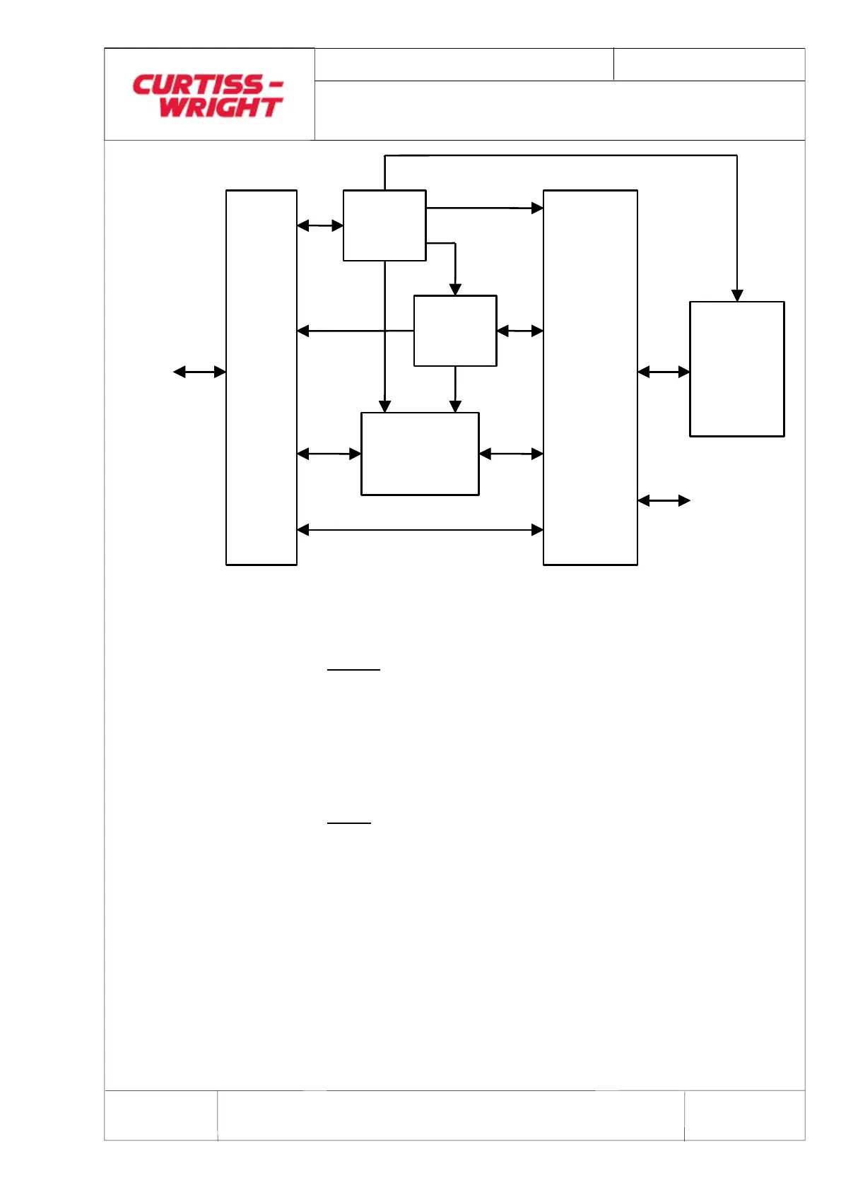
EXTERNAL
INTERFACE
I/O INTERFACE
INTERNAL
DEBUG
INTERFACE
UDIO
PROCESSING
DATA
MANAGEMEN
SYSTEM
SUPERVISOR
CRASH
SURVIVABLE
MEMORY
PSU
MODULE
Figure 4 DAFR System Block Diagram
1.1.5 Interface Description
General
All status outputs and control inputs with the exception of
VOICE ERASE and RECORD ON operate with respect to
CHASSIS GROUND.
The DAFR is direct mounted to an aircraft bulkhead/ equipment
shelf.
NOTE:
Anti-vibration mounting is not required.
Electrical connection is automatically achieved via the single
connector mounted at the rear of the unit (see Installation
Drawing Figure 5 and Figure 6).
The main external electrical connector is a 66-pin MIL-C38999
series III style receptacle, P&G part number W107820. Pin
connections and external cable requirements are shown in
Table 2. The connector provides Lightning Transient Protection
and EMC filtering.
 Loading...