Mar 2017 Page 49
© Penny & Giles Aerospace Ltd. No part of this work may be reproduced or distributed by any
means without prior permission in writing from the copyright owner.
DATA ACQUISITION FLIGHT RECORDER Type D51615-202-XXX or D51615-
202-XXX-090- with CCU Type D51616-XXXX and CAM Type D51623-XXXX
Installation and Operating Manual with Illustrated Parts
List
Commercial in Confidence
PIM434-I
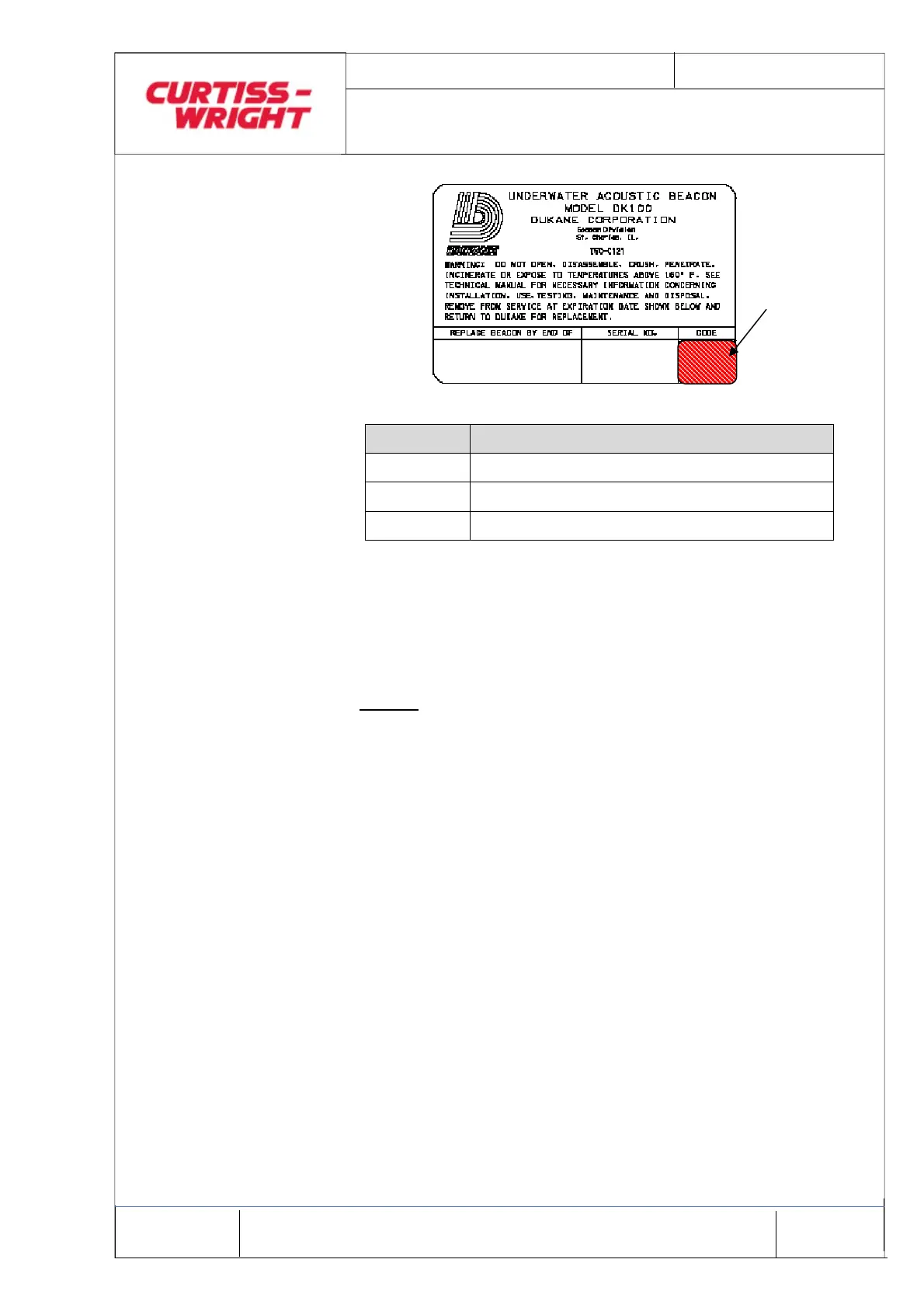
Figure 10 Typical Beacon Label
CODE MINIMUM ACCEPTABLE VOLTAGE
A 3.55 VOLTS
B 2.97 VOLTS
C 2.97 VOLTS
Table 6 Beacon Voltage Code and Minimum Acceptable Voltage
6.4.3 ULB Test
At the intervals specified, and at any other time considered
necessary, the ULB is to be tested as follows:
NOTES:
1. The beacon should be tested both prior to and
after installation onto the DAFR.
2. Alternate test equipment and test procedures may
be used.
(1) Set the switches on the Dukane Ultrasonic Test Set
Model 42A12A, or equivalent, as follows:
(a) INT/EXT switch to INT
(b) kHz TUNING to between 35 kHz and 40 kHz
(c) Gain control clockwise to MAX.
(2) Place the Test Set approximately 30cm (12 inches) from
the ULB.
(3) Short circuit the central pin of the ULB to the beacon
case.
(4) Check that an audible signal is heard from the Test Set.
BATTERY
CODE