Mar 2017 Page 47
© Penny & Giles Aerospace Ltd. No part of this work may be reproduced or distributed by any
means without prior permission in writing from the copyright owner.
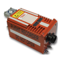
DATA ACQUISITION FLIGHT RECORDER Type D51615-202-XXX or D51615-
202-XXX-090- with CCU Type D51616-XXXX and CAM Type D51623-XXXX
Installation and Operating Manual with Illustrated Parts
List
Commercial in Confidence
PIM434-I
6.3 FUNCTIONAL CHECK
NOTE:
The procedure described herein refers to installations
with a separate Penny & Giles Aerospace Ltd Cockpit
Control Unit type D51616-XXXX.
6.3.1 Procedure:
(1) Momentarily operate the TEST pushbutton on the
Control Unit.
(2) Check that the associated CVR FAIL and FDR FAIL
indicators illuminate for approximately eight seconds
and then extinguish.
(3) If either of the FAIL indicators remain illuminated the
Functional Check has failed and the DAFR must be
removed from the aircraft for servicing.
NOTE:
The Built-In-Test function is automatic on the
application of power to the DAFR. Provided power has
been cycled pre-flight, it is sufficient just to check for a
‘NO FAIL’ indication.
6.4 ULB PERIODIC INSPECTIONS
ULB periodic inspections are to be carried out at intervals not
exceeding six months elapsed time or as agreed with the
relevant Regulatory Authority. Carry out the check as follows:
6.4.1 ULB Switch Cleaning
CAUTION:
DIRT ON THE ULB SWITCH CONTACTS CAN CREATE A
PATH FOR BATTERY CURRENT DRAIN.
At the intervals specified, and at any other time considered
necessary, the ULB switch is to be cleaned as described in
para 8.3 ULB Switch Cleaning.
6.4.2 ULB Battery Test
At the intervals specified, and at any other time considered
necessary, the ULB battery is to be tested as follows: