Mar 2017 Page 14
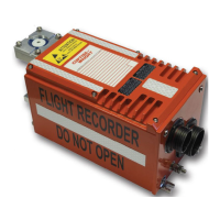
DATA ACQUISITION FLIGHT RECORDER Type D51615-202-XXX or D51615-
202-XXX-090 with CCU Type D51616-XXXX and CAM Type D51623-XXXX
Installation and Operating Manual with Illustrated Parts
List
Commercial in Confidence
PIM434-I
© Penny & Giles Aerospace Ltd. No part of this work may be reproduced or distributed by any means
without prior permission in writing from the copyright owner.
PIN SIGNAL
CABLE
REQUIREMENTS
NOTES
60 0V Signal
2
24 AWG
61 Power In Return
1
22 AWG
62 Reserved
63 Reserved
64 Potentiometer #4 +3.3V Configurable
5
65 Reserved
66 Potentiometer #4 Return Configurable
5
NOTES:
1. Link to be less than 30 cm (12") on aircraft (Pins 4,
5, 8 and 61)
2. Link to be kept as short as possible (Pins 59 and 60).
3. Category 5 Foil Twisted Pair (Pins 20 to 21 and 22 to
23).
4. Force IP Address (Pin 33)
5. Refer to Part 4: Customer Configurations
Specifications for details relating to the recorder
configuration.
Equipment Inputs
Power Supply
The nominal power supply to the DAFR shall be +28VDC with
aircraft electrical power characteristics of RTCA/DO-160F,
Section16, Category A.
Equipment Operation: +18.0 VDC to +32.2VDC
Power Consumption: 15W maximum.
The DC supply to the DAFR should be protected by a 5A circuit
breaker. The DAFR is protected against accidental reversal and
loss or degradation of the +28VDC supply.
NOTE:
The type of circuit breaker used, together with any other
protection devices, must be capable of passing an inrush
current of 30 amps for 2 milliseconds without tripping.
 Loading...