Curtiss-Wright | Tritex II AC 90, 115 Rev. X PN39892 7/12/22
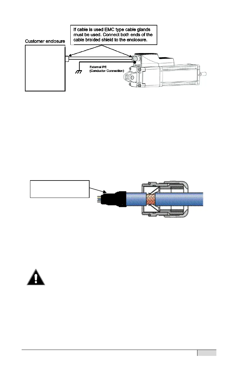
Grounding Diagram
Shielding
In order to meet the European EMC Directive for an installation and to
provide immunity from radio frequency (rf) interference and to minimize rf
emissions, the power and I/O wiring or cables must be shielded. Metallic
conduit (solid or flexible) can serve as a shield. Shields must be
connected to the enclosure at the entry / exit point. This is most easily
accomplished with EMC type cable glands.
When the “I” connector option and Exlar cables are used this function
is included in the cable/ connector construction at the actuator end.
Avoid Loose Conductive Material
Always apply tape or heat shrink to the end of the shield to
prevent strands of the braided shield from breaking off and
shorting internal electronics or compromising spacing.
NPT Connections
When the connector option “N” is selected the Power and I/O wiring
access holes are machined for ½ inch NPT fittings. Teflon tape or the
equivalent must be used to seal the NPT thread connections to maintain
UL Type 4 enclosure ratings. Due to the enclosure rating requirement,
Tape or heat shrink
applied to cable end