Curtiss-Wright | Tritex II AC 90, 115 Rev. X PN39892 7/12/22
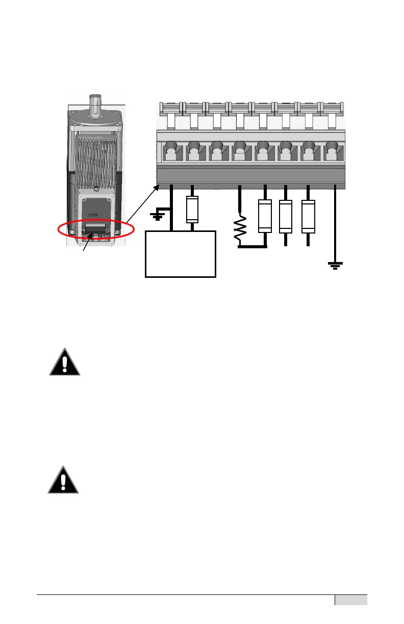
Power Terminal Connections
Refer to the diagram below for connections to the main power terminal
block.
Internal Power Terminal Block Connections
Check All Connections before Applying Power
Connecting AC Power to any terminals other than L1 and
L2 will severely damage the actuator and such damage is
not covered by warranty. Connecting a 24 Vdc source to L1, L2, R1 or
R2 in error can result in a shock hazard or damage at connected
equipment. R1 and R2 may connect only to a braking resistor.
Dangerous Voltages Present On R1 and R2 terminals
and Connector Pins #4 and #5 with I connector option
R1 and R2 terminals have dangerous voltages present
under normal operation and for up to 6 minutes after main power is
disconnected. With the I connection option these terminals come wired to
Pins #4 and #5 of the M23 Power connector. Conductors attached to
these pins must be terminated at the user end of the cable to avoid
shorting even when a braking resistor is not used.
100-240 VAC
Braking
Resistor
Logic supply
(Optional)