Curtiss-Wright | Tritex II AC 90, 115 Rev. X PN39892 7/12/22
Units except those with Option IA4 for isolated 4-20mA signals have
standard analog signals assigned to pins K, L, N and O as shown in the
table. On units with Option IA4, the 4-20mA signals are wired to pins K,
L, N and O as shown in the table and the standard analog signals are not
wired out though they exist at the Terminal Board.
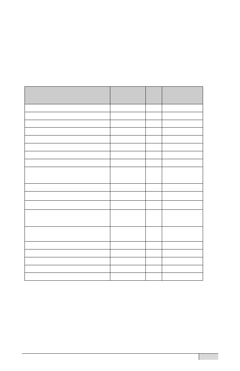
The following table shows the function, insulation color for internal
wiring between the Terminal Board and connector in the wiring
compartment, the connector pin assignment in both halves of the
connector and the T2IOC cable insulation colors.
Internal
Cable
Field I/O Power (+24 V)
(also Brake Power)
Brown/Green F Red
ANALOG IN+ / + 4-20mA Input
ANALOG IN– / – 4-20mA Input
ANALOG OUT+ / + 4-20mA
Output
Grey/Brown N Blue
ANALOG OUT reference / –
4-20mA Output
Violet O Orange
Note: See cable section for T2IOC cable details
 Loading...