1155
6699
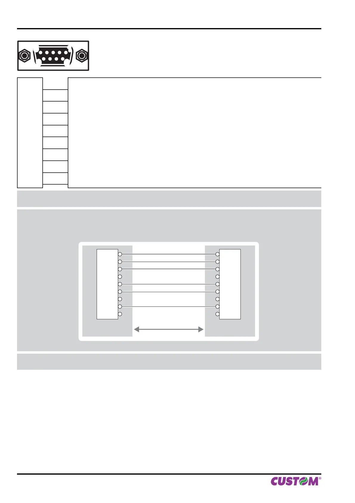
RS232 SERIAL INTERFACE
Female DB9 connector
J3
1 DTR (out)
When “1”, printer is fed
2 TX (out)
During transmission, oscillates between “0” and “1” depending on data
3 RX (in)
During reception, oscillates between “0” and “1” depending on data
4 n.c.
5 GND
6 DTR (out)
When “1”, printer is fed
7 n.c.
8 RTS-O (out)
When “1”, printer is ready to receive data
9 +5VO
Note: Given the presence of the RS232 standard, logic value “0” corresponds to a voltage level of between +3 Vdc
and +15 Vdc and logic value “1” corresponds to a voltage level of between -3 Vdc and -15 Vdc.
Note: VKP80II > PC connection
The following pictures show an example of connections between the printer and a personal computer using a 9
pin female serial connector:
DEVICE PC
DCD
RXD
TXD
SIGNAL GND
DSR
CTS
DB9
1
2
3
4
5
6
7
8
9
DB9
1
2
3
4
5
6
7
8
9
Note: When use a serial cable, we recommend the installation of a ferrite core on the serial cable.
3. INSTALLATION
20 VKP80II User Manual