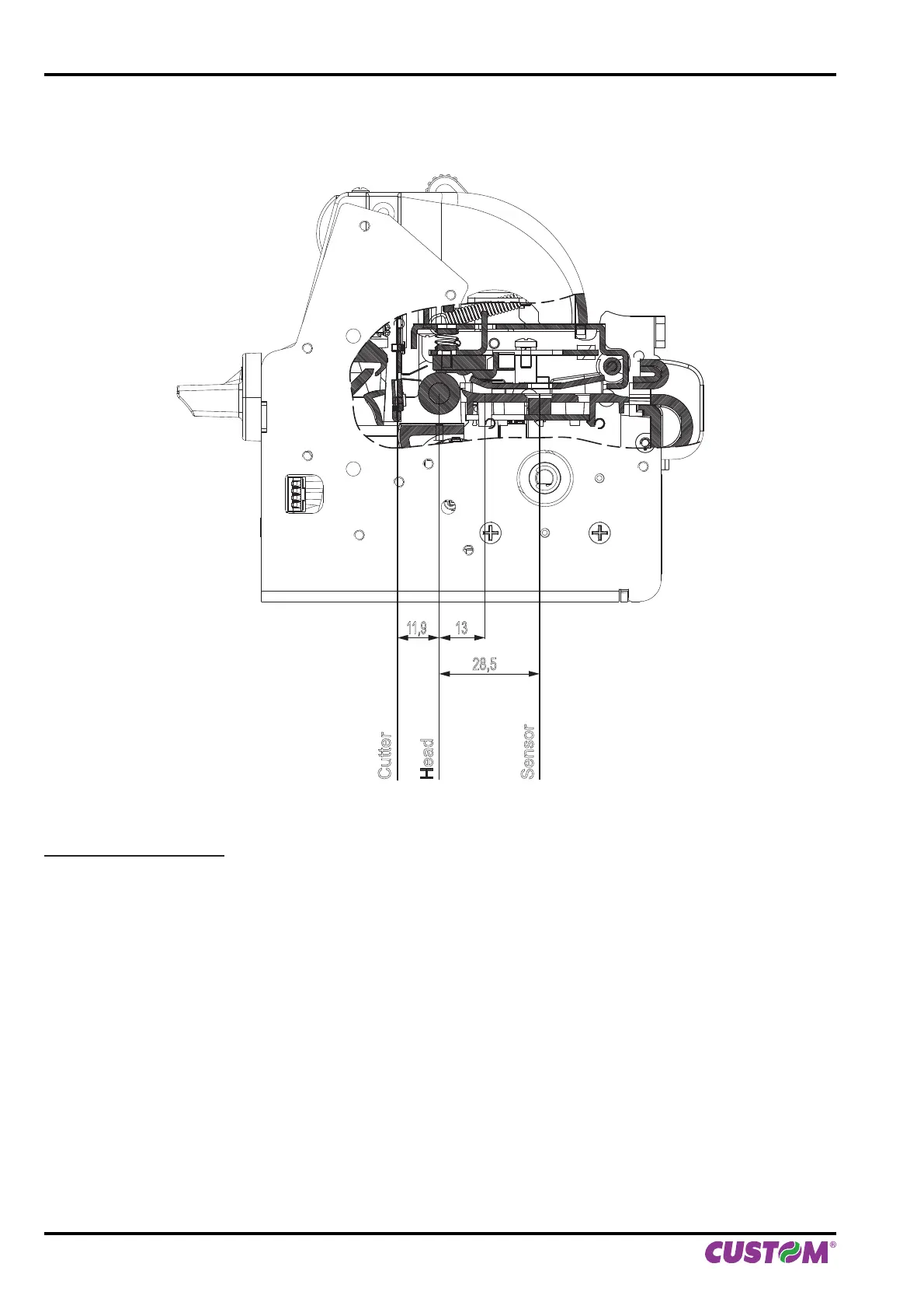
The following fi gure shows a section of the device with the distances between the alignment sensors, the printing
head and the cutter (cutting line):
28,5
13
11,9
Cutter
Head
Sensor
ESC/POS™ EMULATION
To de fi ne the alignment point you need to set the printer parameters that compose the numerical value of the “Notch
Distance” parameter.
For example, to set a notch distance of 15 mm between the notch and the alignment point, the parameters must be
set on the following values:
Notch Distance [mm x 10] : 1
Notch Distance [mm x 1] : 5
The “Notch Distance” parameter, may be modifi ed as follows:
• during the Setup procedure of the device (see chapter 5)
• by using the $1D $E7 command (for more details, refer to the Commands Manual)
• by driver.
10. ALIGNMENT
70 VKP80II User Manual