22
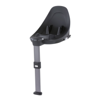
Removal of the base
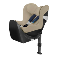
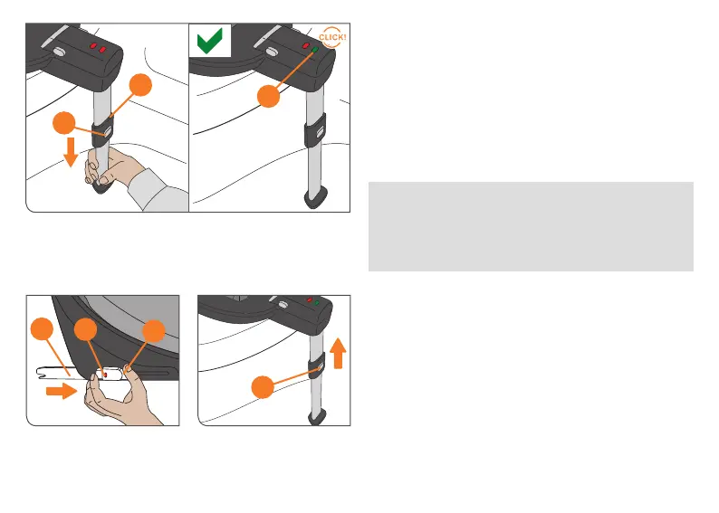
Adjusting the supporting leg
Carry out the installation steps in the reverse order.
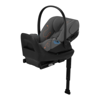
• 8QORFNERWK,62),;FRQQHFWRUVWKURXJKSXVKLQJWKH
EXWWRQVDQGVLPXOWDQHRXVO\DQGSXOOWKHPRXWRI
the ISOFIX connect guides.
• 3XVKWKHFRQQHFWRUVEDFNLQWRWKHRULJLQDOSRVLWLRQ
• %\SUHVVLQJWKHDGMXVWPHQWEXWWRQ\RXFDQSXVK
back the supporting leg into its original position and then
fold it back to save space.
3XVKWKHDGMXVWPHQWEXWWRQXSZDUGVRQWKHVXSSRUW
leg and press it to pull the support leg. Pull the supporting
OHJRXWXQWLOLWWRXFKHVWKHYHKLFOHÀRRU$IWHUWKLVSXOO
the foot out to the next locking position to ensure optimal
IRUFHWUDQVPLVVLRQ7KHVXSSRUWLQJOHJLQGLFDWRURQWKH
base will show GREEN and a characteristic ‚CLICK‘ may
be heard.
!
WARNING!7KHVXSSRUWLQJOHJPXVWDOZD\VEH
in direct contact with the vehicle floor. There must be
no objects or spaces between the vehicle floor and
the supporting leg. If there are storage compartments
in the floor of the vehicle you must contact the
vehicle manufacturer.
NOTE!0DNHVXUHWKDWWKHEDVHVWLOOUHVWVÀDWRQWKHFDU
seat.
14
15
16
17
20
19
19
 Loading...