Cybex Pro+ Treadmill Service Manual
Service
Page 4-35
Using wire cutters, cut the cable at its center near the junction and pull both ends out of the F.
treadmill. NOTE: Pull the upper end up and out and the lower end down and out.
NOTE: Display cables have a revision number label so that you can verify that you have the latest
revision of the cable.
6. Attach the new display cable.
Connect the display cable (P3 and P8) to the A.
upper display board. See Figure 27.
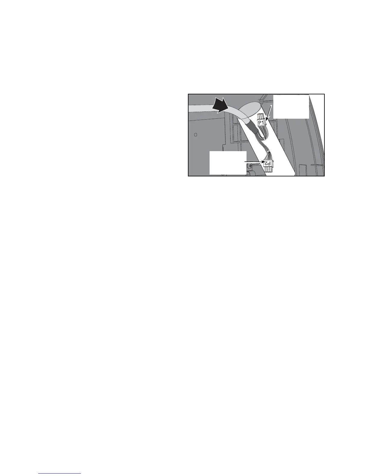
Locate the P1 and P2 end of the display B.
cable. See Figure 28.
Push the P2 connector down into the top C.
handrail hole with the P1 connector pointing
up. See Figure 28.
Push the display cable down through the D.
handrail and out the handrail’s bottom hole.
NOTE: Twisting the cable as you push will
help it go through.
Push the display cable down through the E.
upright and out the exit hole. NOTE: There is a black line on the display cable to show you how
far to pull out the cable. When you see the line, stop pulling the cable out.
Route the cable into the access hole. F.
Connect the display cable to the lower control board at P1 and P2.G.
7. Secure the cable.
Using a Phillips screwdriver, open the clip described in step 5D and secure the cable in A.
the clip.
Locate the line on the display cable described in step 6D and tie the cable with the wire tie B.
near the bottom of the upright.
Open the wire holder at the junction, put the cable inside and close the wire holder. C.
Check to see that all of the connectors are connected fi rmly in their proper place.D.
Place the lower board shield in position and push the clips down. E. NOTE: The clips will snap in.
8. Secure the left junction covers.
Using a Phillips screwdriver, tighten the three screws that hold the junction covers in place.A.
9. Secure the motor cover.
Lower the motor cover center into position. See Figure 2.A.
Using a Phillips screwdriver, tighten the three screws on each side. B. NOTE: Be sure the screws are
catching the center motor cover’s holes.
10. Secure the console back.
While being sure not to pinch any cables, attach the console back to the console front with A.
the fi ve Phillips screws.
Figure 28
Large P2
Connector
Down
Small P1
Connector
Up