MNL-00007 [3] Proprietary and Confidential Page 30 of 63
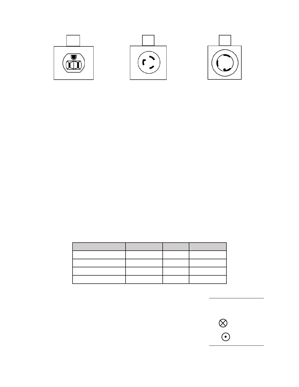
Table 6 NEMA Outlets
21.2 European CE Electrical Requirements
Daavlin offers the UV Series Phototherapy equipment in a variety of combinations. Units are
available with lamp quantities of 12, 16, 24, and 28 with various combinations of UVA,
Narrowband UVB, and Broadband UVB. While the type of ultraviolet lamp (UVA or UVB) does
not influence the electrical requirements, the number of lamps contained in a unit does determine
the amperage and wiring necessary to safely support operation. This device is intended for
stationary use while permanently connected to mains electrical supply. This device requires a
dedicated service. All wires should terminate directly at the service and must not power any
other equipment. A non-dedicated service may result in invalidation of the warranty. The
electrical junction box must be installed in accordance with local codes, before the unit arrives.
Daavlin specifies that the junction box must be equipped with a safety disconnect switch. This
enclosure should be mounted to the wall against which the unit will stand at a height of four feet
from the floor. Follow these specifications and all national and local electrical codes when
preparing the electrical supply prior to the installation of a UV Series Device.
Note: This unit should be on a dedicated circuit.
Note: Daavlin UV Series X and UV Series T Phototherapy equipment contain no operator
replaceable parts.
21.3 Circuit Breaker
Each UV Series unit is equipped with a circuit breaker that is located
under the frame, at the back-right hand side of the machine. Its location
is indicated by the circuit breaker label (right). When setting up your
unit, ensure that the breaker is in the ON position.
21.4 Unpacking and Assembly