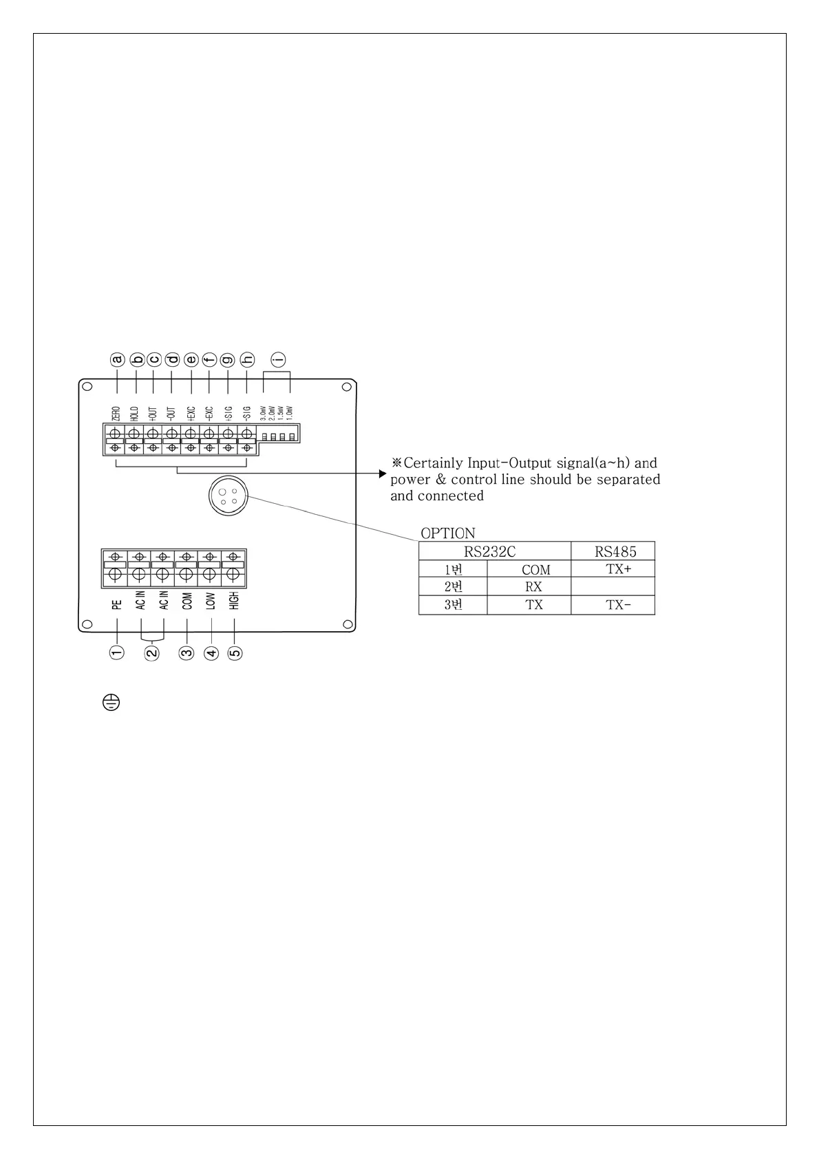
5. Back panel
Make sure the terminal site and its use, and wire separately from a lot of nosing
wiring.
Press protruded button on the top of terminal stand, and insert it into the hole on the
lower part of it to the end.
Then, pull it gently to make its certainty.
(Suitable cable is 0.5-1. Linking cable must be brazing or used with I terminal)
①
PE : Ground Terminal (In other way independent ground connection )
② AC IN : Main Power Supply Wiring Terminal
③ COM : Relay Output lower limit and upper limit Common Terminal
④ LOW : Relay Output lower limit Connection Terminal
⑤ HIGH : Relay Output Upper Connection Terminal
ⓐ ZERO : ZERO KEY FOR External Input Mode Selection
The data is zero when connect –OUT Terminal.
This key does not work when is using HOLD DATA .
ⓑ HOLD : HOLD KEY FOR External Input Mode Selection
The data is held when connect –OUT Terminal.
(Peak Hold : Display is
display will be replaced w
Sample Hold : Display is key is pressed or command input is ON.)
The data is re
ⓒ +OUT : Analog O
Locked when HOLD key is pressed or command input is ON. But,
hen new peak data is entered.
Locked when HOLD
6
set when disconnect –OUT Terminal.
utput Terminal(+)