User's Manual
34
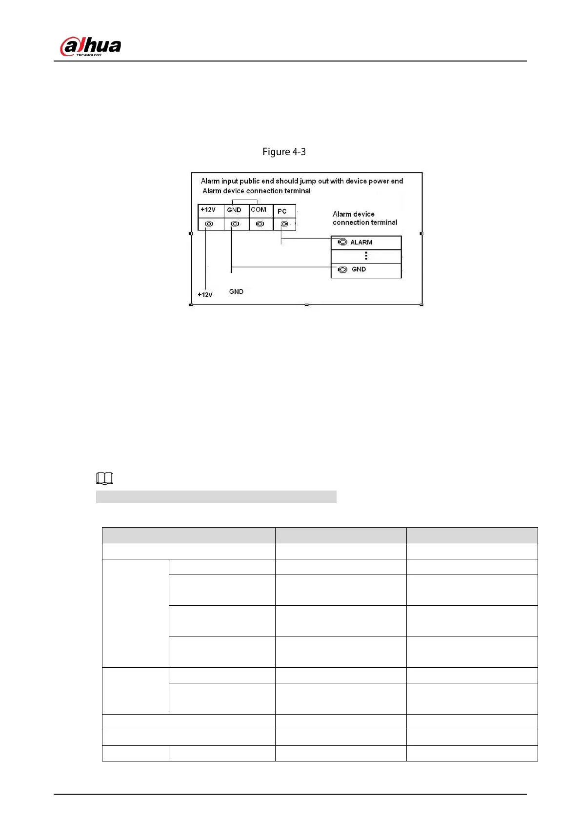
Please parallel connect COM end and GND end of the alarm detector (Provide external power to
the alarm detector).
Please parallel connect the Ground of the DVR and the ground of the alarm detector.
Please connect the NC port of the alarm sensor to the DVR alarm input (ALARM).
Use the same ground with that of DVR if you use external power to the alarm device.
Alarm input
4.3.3 Alarm Output
Provide external power to external alarm device.
To avoid overloading, please read the following relay parameters table carefully.
RS-485 A/B cable is for the A/B cable of the PTZ decoder.
4.3.4 Alarm Output Relay Parameters
Refer to the actual product for relay model information.
Table 4-2 Alarm output relay parameters
Material of the touch AgNi+ gold-plating AuAg10/AgNi10/CuNi30
Rating
(Resistance
Load)
Rated switch capacity 30 VDC 1 A/125 VAC 0.5 A 24 VDC 1 A/125 VAC 2 A
Maximum switch
power
62.5 VA/30 W 250 VA/48 W
Maximum switch
voltage
125 VAC/60 VDC 125 VAC/60 VDC
Maximum switch
currency
2 A 2 A
Insulation
Between touches 400 VAC 1 minute 500 VAC 1 minute
Between touch and
winding
1000 VAC 1 minute 1000 VAC 1 minute
Turn-on Time 5 ms max 5 ms max
Turn-off Time 5 ms max 5 ms max
Longevity Mechanical 1×10
7
times 5×10
6
times
 Loading...