User's Manual
17
6
RS-485
communication
port
Connects to the control devices such as speed dome PTZ. RS-485_A
port is connected by the cable A and RS-485_B is connected to the
cable B.
7 VGA port Outputs analog video data to the connected display with VGA port.
8 USB port
Connects to external devices such as USB storage device, keyboard
and mouse.
9 Power input port Inputs 12 VDC power.
10
Power cable
fastener
Use clamp to secure the power cable on the DVR in case there is any
loss.
11
Ground terminal.
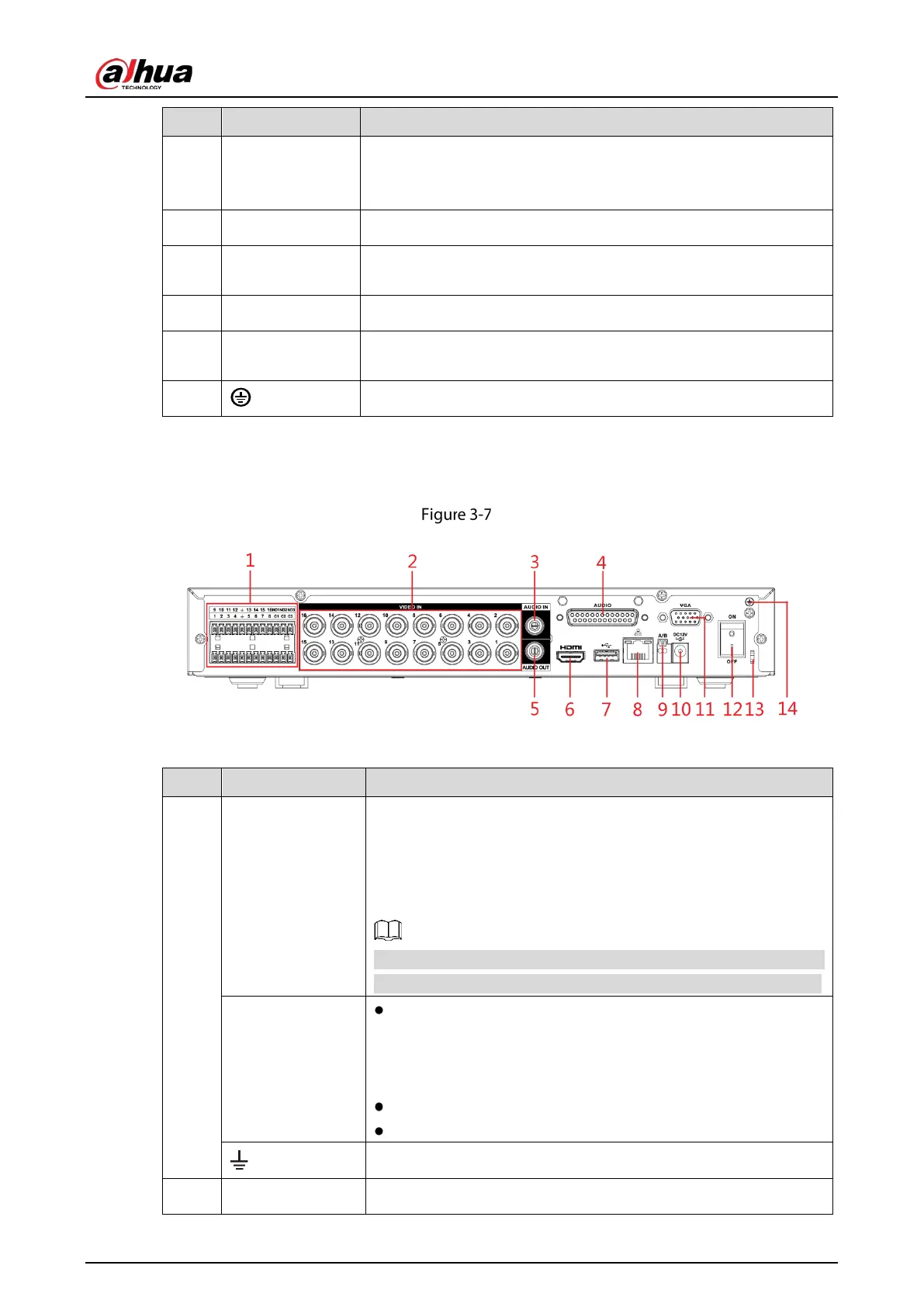
3.2.2 DHI-XVR5116H-4KL
Rear panel
Table 3-7 Rear panel description
1
Alarm input port
1–16
Four groups of alarm input ports (Group 1: port 1 to port 4; Group
2: port 5 to port 8; Group 3: port 9 to port 12; Group 4: port 13 to
port 16). These ports receive the signal from the external alarm
source. There are two types: NO (Normally Open) and NC
(Normally Closed).
When your alarm input device is using external power, make sure
that the alarm input device and the Device have the same ground.
Alarm output port
1–3 (NO1–NO3;
C1–C3)
Three groups of alarm output ports (Group 1: port NO1–C1,
Group 2: port NO2–C2, Group 3: port NO3–C3). These ports
output alarm signal to the alarm device. Make sure that
power supply to the external alarm device.
NO: Normally open alarm output port.
C: Alarm output public end.
Ground.
2 Video input port Connects to analog camera to input video signal.
 Loading...