SQLC-214-097
10
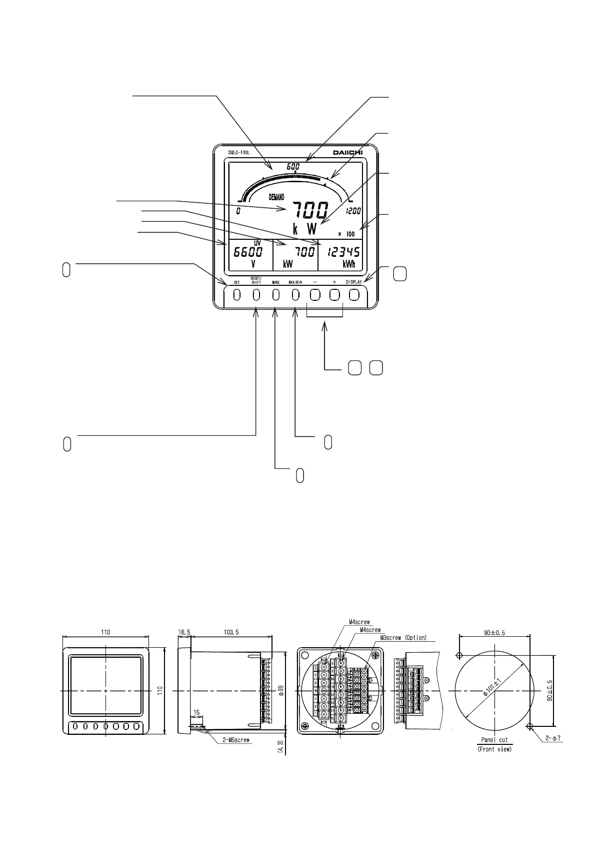
2. The name and function of each part
3. Preparation
3.1 Installation
Mount the unit by the attached M5 nuts to a panel of thinner than 10mm, referring to the following external
dimensions drawing and panel cutout. Fasten these nuts with tightening torque 2.75 to 3.82N・m.
● Dimension diagram
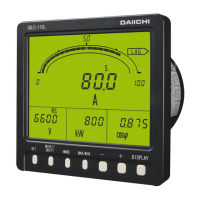
(1) Multi-meter
This switch resets various alarms.
And, in the maximum and the minimum measurement
display, it is used as a switch that resets the
maximum and the minimum value.
In setting mode, it is used as a switch to which
a setting item is shifted.
Bar graph display
The measurement value of the main monitor
is indicated by the analog.
(Setting which does bar graph display
of the measurement value of sub-monitor
is also possible.)
Digital display
Measurement monitor can watch
4 elements at the same time.
・Main monitor
・Sub-monitor (Right)
・Sub-monitor (Center)
・Sub-monitor (Left)
SET
The switch from which integrated
value of the amount of electric
power is switched to normal display
(5 digits of integer) and expansion
indication (integer 2 digits + below
decimal point, 3 digits) variously.
If it is not operated for 10 minutes after a
display change, it will usually return to a
display. It is used also as a switch which
changes to setting mode. If it continues
pushing 3 seconds or more, it will change to
setting mode.
In setting mode, it is used as a switch that
determines a set point.
RESET/
SHIFT
Scale markings
Scale markings is automatically set in a
measurement range.
Unit display
Unit display is automatically set in a
measurement range.
Upper limit (or lower limit) setting index
An upper limit (or lower limit) set point
is displayed.
Multiplying factor display
Multiplying factor is displayed at the time
of an Wh and varh display.
MODE
The switch to which general measurement display (usually) and the
harmonic measurement (voltage and current) display are changed.
In set mode, it is used as a switch that changes a setting item.
DISPLAY
This is a switch which changes the phase
(line) display of current (voltage).
If it is not operated for 10 minutes after a
display change, it returns to the original
phase (line) display. In setting mode, it is
used as a switch that terminates setting mode.
The switch to which measurement displays
element of main monitor is changed.
If it is not operated for 10 minutes after a display
change, it returns to the original measurement display
factor. In set mode, it is used as a switch that
changes a setting value.
MAX/MIN
The switch to which general measurement display (usually)
and the maximum minimum measurement display are changed.
+ -