SQLC-214-097
12
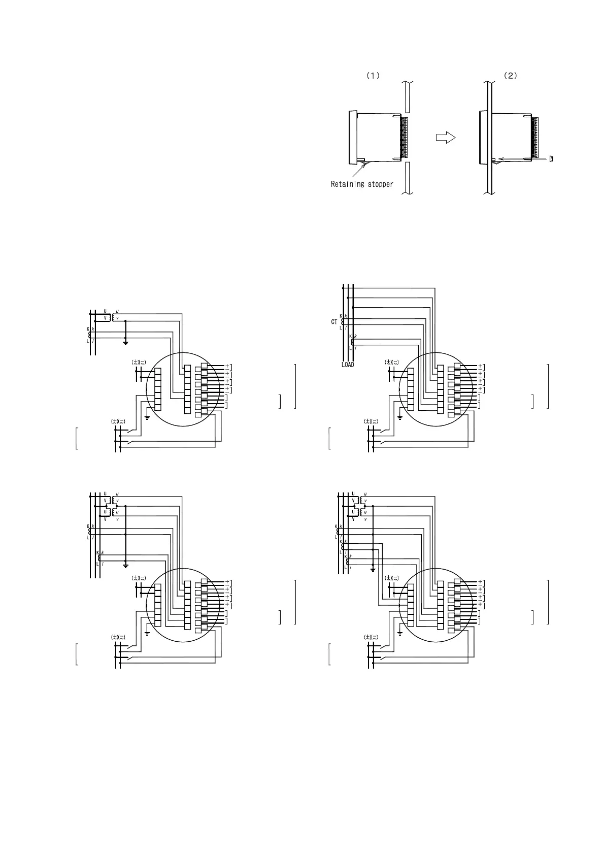
● Installation
(1) A product is put in a cut hole of a panel from a front.
A body is inserted until it exceeds retaining stopper
of the lower base.
(2) Please fix a product certainly with attached M5 flange
nut for installation. Please give a tightening
torque as 2.75 to 3.82N・m.
3.2 Connections
Please perform connection after referring to the following wiring diagram.
● Connection drawing (
16
)
(1) 1φ2W (2) 1φ3W
( )
( )
13
( )
14
EXT.INPUT1
EXT.INPUT2
7
5
6
CT
LOAD
VU
VT
AUX.SUPPLY
2
1
ANALOG OUTPUT3
21
20
ANALOG OUTPUT4
CONTACT OUTPUT1
CONTACT OUTPUT2
27
28
29
12
13
22
23
24
25
26
15
ANALOG OUTPUT1
ANALOG OUTPUT2
8
9
16
17
18
19
ANALOG OUTPUT3
CONTACT OUTPUT2
CONTACT OUTPUT1
ANALOG OUTPUT4
ANALOG OUTPUT2
ANALOG OUTPUT1
UNW
AUX.SUPPLY
EXT.INPUT1
EXT.INPUT2
13
( )
14
( )
( )
13
21
20
7
5
6
27
15
28
29
14
12
13
26
25
24
23
22
1
2
8
9
19
18
17
16
( )
15
( )
13
(3) 3φ3W (2VT,2CT) (4) 3φ3W (2VT,3CT)
( )
( )
13
( )
14
EXT.INPUT2
EXT.INPUT1
LOAD
7
6
AUX.SUPPLY
1
5
2
CT
VU W
VT
ANALOG OUTPUT1
ANALOG OUTPUT2
ANALOG OUTPUT4
CONTACT OUTPUT1
CONTACT OUTPUT2
ANALOG OUTPUT3
13
25
15
14
27
29
28
26
9
18
12
20
21
22
23
24
19
8
16
17
15
ANALOG OUTPUT1
ANALOG OUTPUT2
ANALOG OUTPUT4
CONTACT OUTPUT1
CONTACT OUTPUT2
ANALOG OUTPUT3
AUX.SUPPLY
LOAD
EXT.INPUT2
EXT.INPUT1
( )
13
( )
14
( )
13
W
CT
UV
VT
13
25
7
6
15
14
27
29
28
26
1
5
2
3
4
9
18
12
20
21
22
23
24
19
8
16
17
15
( )
13
( )