8 | Piping installation
Installer reference guide
69
ERGA04~08EAV3(A) + EHVZ04+08S18+23EA6V+9W
Daikin Altherma 3 R F
4P629093-1 – 2020.08
T1
M1
T1
M1
T2
M2
T3
M3
M
FHL1
FHL2
FHL3
M2 M3
T2 T3
HPC1 HPC2 HPC3
a b c
g hf
d e
i
i
hh
h
j
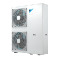
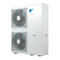
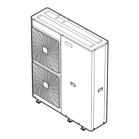
a Outdoor unit
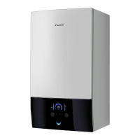
b Indoor unit
c Heat exchanger
d Backup heater
e Motorised 3‑way valve (mixing the main zone)
f Additional pump
g Main pump
h Shut-off valve
i Collector (field supply)
j Overpressure bypass valve (delivered as accessory)
FHL1...3 Floor heating loop (field supply)
HPC1...3 Heat pump convector (field supply)
T1...3 Individual room thermostat (optional)
M1...3 Individual motorised valve to control loop FHL1...3 and HPC1...3 (field supply)
INFORMATION
The pump of the additional zone ensures that the minimum flow rate for correct
operation of the unit is guaranteed.
Maximum water volume
Use the following graph to determine the maximum water volume for the
calculated pre-pressure.
0.3
0.5
1
1.5
2
2.4
5020 100 150 200 250 290
a
b
a Pre-pressure (bar)
b Maximum water volume (l)
Example: Maximum water volume and expansion vessel pre-pressure

 Loading...

