Installation Manual 3P581074-2D
DGE601A52
21English
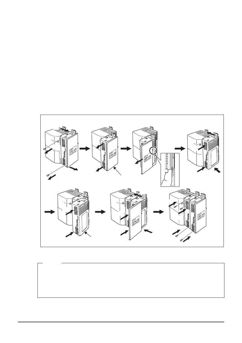
When mounting with screws
(1) Remove the upper and lower DIN rail lock screws of the DGE601A53 which is
furthest from the DGE601A51 or iTM.
(2) Set the upper and lower inter-unit locks to “UNLOCK”.
(3) Pull out the DGE601A53 a little bit.
(4) While pushing the knob attached to the edge of the end cover outward with your
nger, pull the end cover off and remove it.
(5) Return the DGE601A53 to the original position.
(6) Set the upper and lower inter-unit locks to “LOCK”.
(7) Slide in the DGE601A53 to be added along the SLOT rail.
(8) Set the upper and lower inter-unit locks to the “LOCK” position.
(9) Attach the end cover.
(10) Secure all the screw holes on the upper and lower DIN rail locks with screws.
Steps for adding the SLOT
(5)
(6)
(10)
(10)
(10)
(10)
(8)
(8)
(9)
(9)
(6)
(3)
(1)
(2)
(3)
(7)
(4)
(2)
(1)
(7)
(5)
End cover
DGE601A53
“UNLOCK”
“LOCK”
“UNLOCK”
“LOCK”
“LOCK”
“LOCK”
NOTE
• Turn OFF the [TERM] switch of the DGE601A53 which originally had the [TERM]
switch set to ON.
• Turn ON the [TERM] switch of the DGE601A53 which is furthest from the
DGE601A51 or iTM.
01_EN_3P581074-2D.indd 21 2021/06/25 14:12:10
 Loading...