unit installation
IM 930-6 •EnnityVerticalWaterSourceHeatPumps 10 www.DaikinApplied.com
Piping
1. Allunitsshouldbeconnectedtosupplyandreturn
pipinginatwo-pipereversereturnconguration.A
reversereturnsystemisinherentlyself-balancing
andrequiresonlytrimbalancingwheremultiple
quantitiesofunitswithdifferentowandpressuredrop
characteristicsexistinthesameloop.Checkforproper
waterbalancebymeasuringdifferentialtemperature
readingacrossthewaterconnections.Forproper
waterow,thedifferentialtemperatureshouldbe12°F
to14°F(5°Cto8°C)forunitsincoolingmode.
Adirectreturnsystemmayalsowork,butproperwater
owbalancingismoredifculttoachieveandmaintain.
2. Thepipingcanbesteel,copperorPVC.
Note: If using PVC (schedule-40) construction grade
pipe or better, use the manufacturers recom-
mended high temperature adhesive. With PVC
piping the appropriate number of hanger brackets
must be used to help prevent sagging.
3. Supplyandreturnrunoutsusuallyjointheunitviashort
lengthsofhighpressureexiblehosewhicharesound
attenuatorsforbothunitoperatingnoiseandhydraulic
pumpingnoise.Oneendofthehoseshouldhave
aswivelttingtofacilitateremovalforservice.Hard
pipingalsocanbebroughtdirectlytotheunit.This
optionisnotrecommendedsincenovibrationornoise
attenuationcanbeaccomplished.Thehardpiping
musthaveunionstofacilitateunitremoval.SeeFigure
8,Figure9,andFigure10fortypicalpipingdetails.
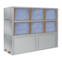
Figure 8: Typical Vertical Unit Piping
4. Someexiblehosethreadedttingsaresuppliedwith
sealantcompound.Ifnot,applyTeontapeforatightseal.
5. Supplyandreturnshutoffvalvesarerequiredat
eachunit.Thereturnvalveisusedforbalancingand
shouldhavea“memorystop”sothatitcanalways
beclosedoffbutcanonlybereopenedtotheproper
positionfortheowrequired.
6. Donotconnectanyunittothesupplyandreturnpiping
untilthewatersystemhasbeencleanedandushed
completely.Afterthecleaningandushinghastaken
place,theinitialconnectionshouldhaveallvalveswide
openinpreparationforwatersystemushing(see
"Cleaning&FlushingWaterSystem"onpage8).
7. Condensatepipingcanbesteel,copperorPVC.
Eachunitincludesacondensateconnection.
8. Unitsareinternallytrapped.
9. Donotlocateanypointinthedrainsystemabove
thedrainconnectionofanyunit.
10. Automaticowcontrolleddevicesmustnotbe
installedpriortosystemcleaningandushing.
11. Ahighpointofthepipingsystemmustbevented.
12. Checklocalcodefortheneedfordielectricttings.
Note: Do not over-torque ttings. The maximum torque
without damage to ttings is 30 foot pounds. If a
torque wrench is not available, use as a rule of
thumb, nger-tight plus one quarter turn.
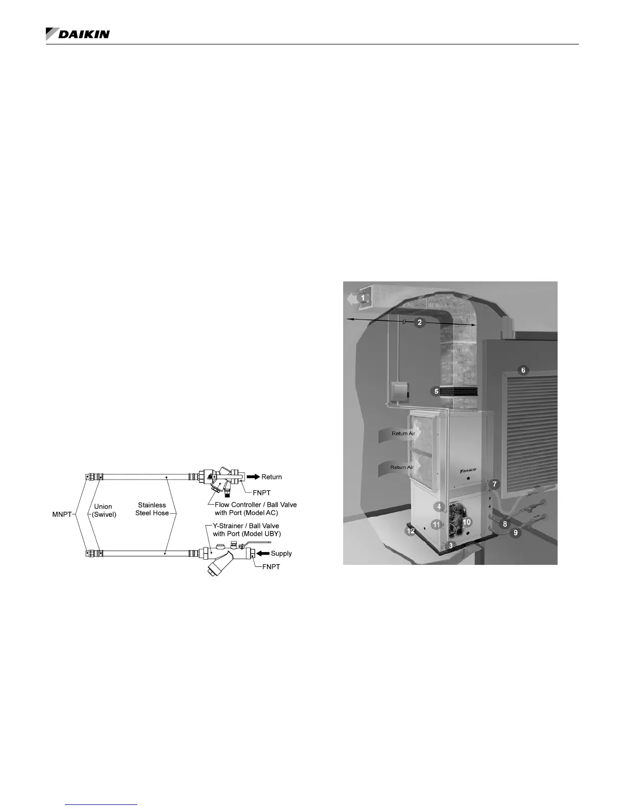
Figure 9: Typical Vertical Installation and Unit Piping
1 SupplyAirDucting
2 AcousticalThermalLining(10ft.)
3 LineVoltage-7/8"(22mm)Hole
4 LowVoltage-7/8"(22mm)Hole
5 FlexibleDuctCollar
6 LouveredDoorforReturnAir
7 CondensateDrainConnection
8 FlexibleReturnHosewithFlowController/BallValve(3/4"FPT)
9 FlexibleSupplyHosewithY-Strainer/BallValve(3/4"FPT)
10 AccessPaneltoController
11 LEDAnnunciatorStatusLights
12 VibrationIsolationPad