therMostat ConneCtions
www.DaikinApplied.com 29 EnnityVerticalWaterSourceHeatPumps• IM 930-6
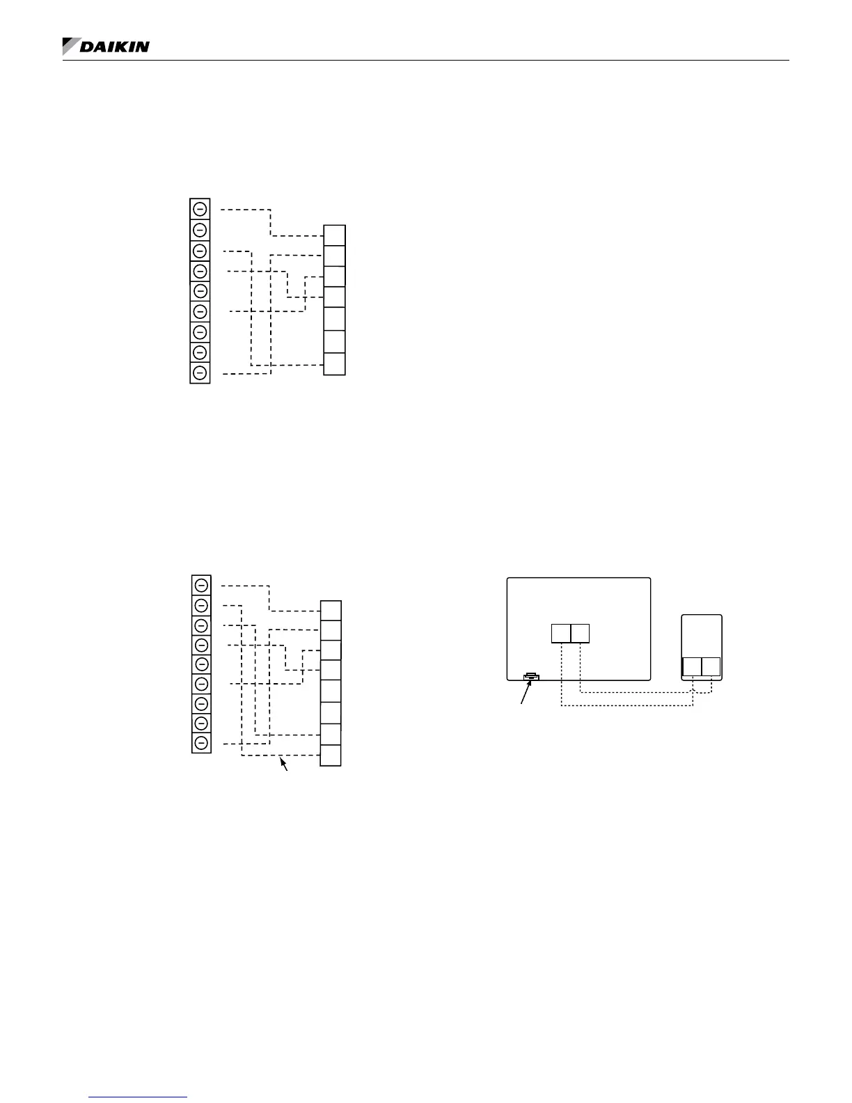
7-Day Programmable Electronic
Thermostat (P/N 668375301)
MicroTech III Unit Control Board
Low Voltage Terminal Strip (Circuit 1)
W1
Y1
W2
Y2
G
Thermostat
Terminals
-
C
TB2
24VAC
Alarm Output
Heat 2
Heat 1
Cool 2
Cool 1
Fan
Tenant Override
24VAC Common
C
O
G
Y1
Y2
W1
W2
A
R
+
R
Notes: Includes Thermostat and Wall Plate.
Refer to the installation, operation & application
guide (LIA265) for thermostat 668375301.
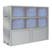
Non-Programmable Electronic
Thermostat (P/N 668375401)
MicroTech III Unit Control Board
Low Voltage Terminal Strip (Circuit 1)
W1
Y1
W2
Y2
G
Thermostat
Terminals
-
C
TB2
24VAC
Alarm Output
Heat 2
Heat 1
Cool 2
Cool 1
Fan
Tenant Override
24VAC Common
C
O
G
Y1
Y2
W1
W2
A
R
+
R
O
*Override(Optional)
Note: Includes Thermostat and Wall Plate.
Refer to the installation, operation & application
guide (LIA266) for thermostat 668375401.
*When remote reset of a lockout condition is re-
quired at the wall thermostat, it will be necessary
to utilize a conductor between terminal "O" on the
wall thermostat to terminal "O" on the MicroTech
III unit controller (non-programmable stat only).
Optional Remote Sensor (P/N
66720401)
1. Removecoverfromremotesensorhousing.
2. Selectanappropriatelocationformountingthe
remotesensor.
3. Mountremotesensorunitusinghardwareprovided.
4. Installtwostrandshieldedwirebetweenremote
sensorandthermostat.Shieldedwiremustbeused.
Note: Do not run remote sensor wire in conduit with
other wires.
• Wire1shouldrunbetweentheS1terminalon
thethermostatandtheS1terminalontheremote
sensor
• Wire2shouldrunbetweentheS2terminalon
thethermostatandtheS2terminalontheremote
sensor
• ConnecttheshieldingofthewiretotheS2terminal
onthethermostat
5. Disablethemainsensor(R12)onthethermostatby
cuttingitfromthecircuitboard.
Figure 24: Optional Remote Sensor Wiring
S1
S2
S1
S2
Cut R12 from
circuit board
Remote Sensor
Thermostat
Wire 1
Wire 2