IM 930-6 •EnnityVerticalWaterSourceHeatPumps 24 www.DaikinApplied.com
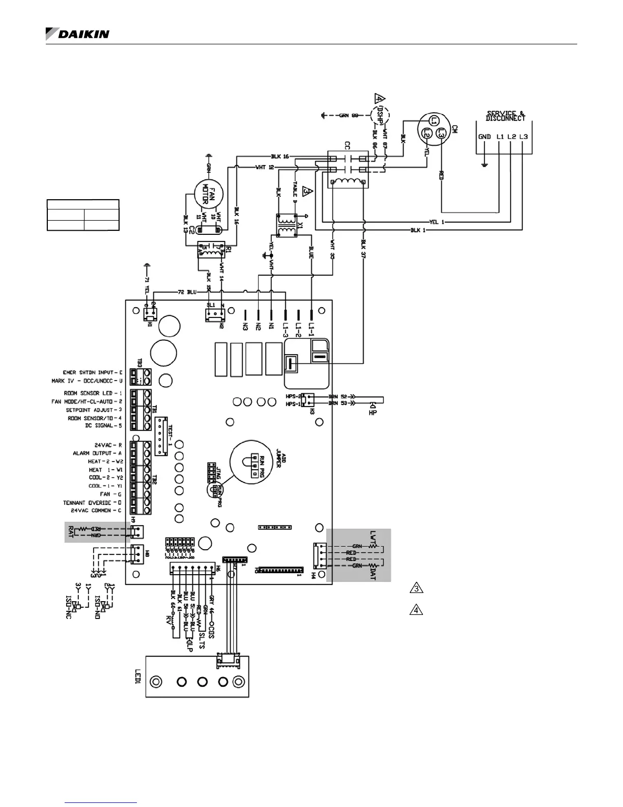
tyPiCal Wiring diagraMs
MicroTech III Unit Controller (Standalone) – 208/230/460/575/60Hz/3-Phase
DrawingNo.668991201
Shownwithoptionaldesuperheater
pumpwiring.
Wiring diagrams are typical. For
the latest drawing version refer to
the wiring diagram located on the
inside of the controls access panel
of the unit.
Table B
208V RED
230V ORG
Note: Gray tinted areas in the wiring diagram: Units with factory installed communication module include Discharge Air Temperature
(DAT) and Return Air Temperature (RAT) sensors shipped loose and are field installed. The Leaving Water Temperature (LWT)
sensor is factory installed.
Legend
Item Description
C1 Capacitor-Compressor
C2 Capacitor-Fan
CC Compressor-Contactor
CM Compressor-Motor
CDS CondensateOverowSensor
DAT DischargeAirTempSensor
HP HighPressureSwitch
HTR ElectricHeaterCartridge
IOEXP I/OExpansionBoard/Harness
ISO-NC IsolationValve-NormallyClosed
ISO-NO IsolationValve-NormallyOpen
LED1 LEDAnnunciator/Harness
LED2 LEDAnnunciator/Harness
LP LowPressureSwitch
SLTS SuctionLineTempSensor
LWT LeavingWaterTempSensor
MIII MicroTechIIIMainBoard
R1 Relay-FanMotor
R2 Relay-ElectricHeat
RAT ReturnAirTempSensor
RV ReversingValveSolenoid
TB1 PowerTerminalBlock
X1 Transformer
_____
StandardUnitWiring
____
OptionalWiring(byothers)
Notes:
Transformer:
Unusedwiretobecapped.
Desuperheateronlyavailableon
115-208-230Vapplications.